4-1 A8C72DC
CABINET DISASSEMBLY INSTRUCTIONS
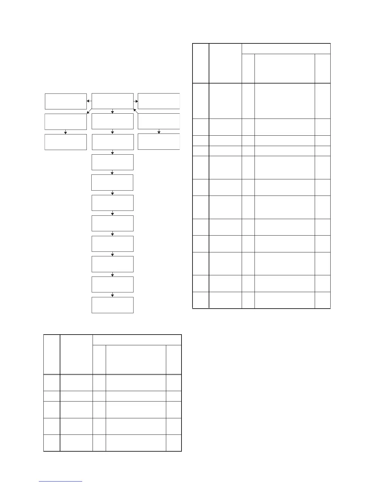
1. Disassembly Flowchart
This flowchart indicates the disassembly steps for the
cabinet parts, and the CBA in order to gain access to
item(s) to be serviced. When reassembling, follow the
steps in reverse order. Bend, route and dress the
cables as they were.
2. Disassembly Method
Note:
(1) Order of steps in procedure. When reassembling,
follow the steps in reverse order. These numbers
are also used as the Identification (location) No. of
parts in figures.
(2) Parts to be removed or installed.
(3) Fig. No. showing procedure of part location
(4) Identification of parts to be removed, unhooked,
unlocked, released, unplugged, unclamped, or
desoldered.
P = Spring, L = Locking Tab, S = Screw,
CN = Connector
* = Unhook, Unlock, Release, Unplug, or Desolder
e.g. 2(S-2) = two Screws (S-2),
2(L-2) = two Locking Tabs (L-2)
(5) Refer to the following "Reference Notes in the
Ta bl e ."
Step/
Loc.
No.
Part
Removal
Fig.
No.
Remove/*Unhook/
Unlock/Release/
Unplug/Unclamp/
Desolder
Note
[1]
Stand
Cover
D1 2(S-1) ---
[2] Neck Cover D1 --------------- ---
[3]
Rear
Cabinet
D1 2(S-2), 3(S-3), 12(S-4) ---
[4]
Stand
Hinge
D1 --------------- ---
[5] Jack CBA
D2
D3
2(S-5), *CN107 ---
[7] Digital Main
CBA Unit
[5] Jack CBA
[13] IR Sensor CBA
[1] Stand Cover
[2] Neck Cover
[3] Rear Cabinet
[14] Function CBA
[16] Speaker(s)
[4] Stand Hinge
[6] Shield Box
[17] Front Cabinet
[10] Main CBA
[9] Shield(T)
[8] FFC Shield
[12] Inverter CBA
[11] Junction CBA
[15] LCD Module
Assembly
[6] Shield Box
D2
D3
2(S-6), (S-7), 3(S-8),
6(S-9), *CN101A,
*CN102A, *CN103A,
*CN104A, *CN4501,
*CN4502
---
[7]
Digital Main
CBA Unit
D2
D3
2(S-10), Connector IC
Card OSU
---
[8] FFC Shield D2 2(S-11) ---
[9] Shield(T) D2 2(S-12), (S-13) ---
[10] Main CBA
D2
D3
4(S-14), (S-15),
*CN106, *CN105A,
*CN802
---
[11]
Junction
CBA
D2
D3
*CN404A ---
[12]
Inverter
CBA
D2
D3
4(S-16), *CN401,
*CN402, *CN403,
*CN451
---
[13]
IR Sensor
CBA
D2
D3
(S-17), *CN301 ---
[14]
Function
CBA
D2
D3
--------------- ---
[15]
LCD
Module
Assembly
D2 --------------- ---
[16] Speaker(s) D2
4(S-18),
Speaker Holder(s)
---
[17]
Front
Cabinet
D2 --------------- ---
↓
(1)
↓
(2)
↓
(3)
↓
(4)
↓
(5)
Step/
Loc.
No.
Part
Removal
Fig.
No.
Remove/*Unhook/
Unlock/Release/
Unplug/Unclamp/
Desolder
Note