14 bintec User’s Guide Technical Data
2
bintec R230aw
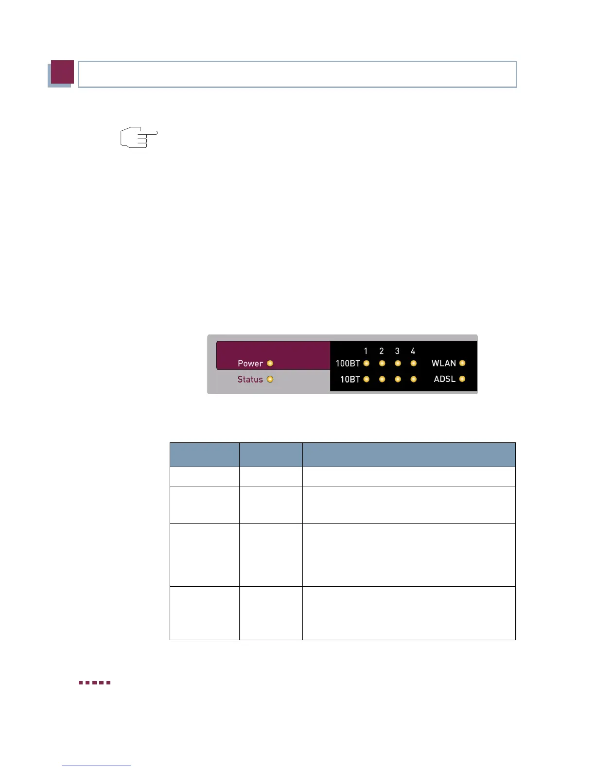
2.3 LEDs
The LEDs on your R Series Gateway indicate the states and the activity of
the gateway.
They are arranged as follows:
Figure 2-1: LEDs on bintec R230aw
In operational mode the LEDs display the following status information:
Note
Antenna Diversity
The two antennas do not have equal funtion. The one named "Main", "Primary"
or "1" (at
R Series devices the antenna next to the power switch) is used for
sending and receiving, the other one only for receiving. The AP (Access point)
verifies, which of the two antennas receives the better signal, which is then
used for decoding.
LED Status Information
Power on Power supply has been connected.
Status on
flashing
The gateway is booting.
The gateway is active.
1 to 4 on
flashing
The gateway is connected to the Ethernet
(100 Mbit/s or 10 Mbit/s respectively).
Data traffic via the Ethernet interface (100
Mbit/s or 10 Mbit/s respectively).
WLAN on
flashing
The WLAN module is active.
Data traffic via the WLAN interface.
 Loading...
