22 bintec User’s Guide Technical Data
3
bintec R232b
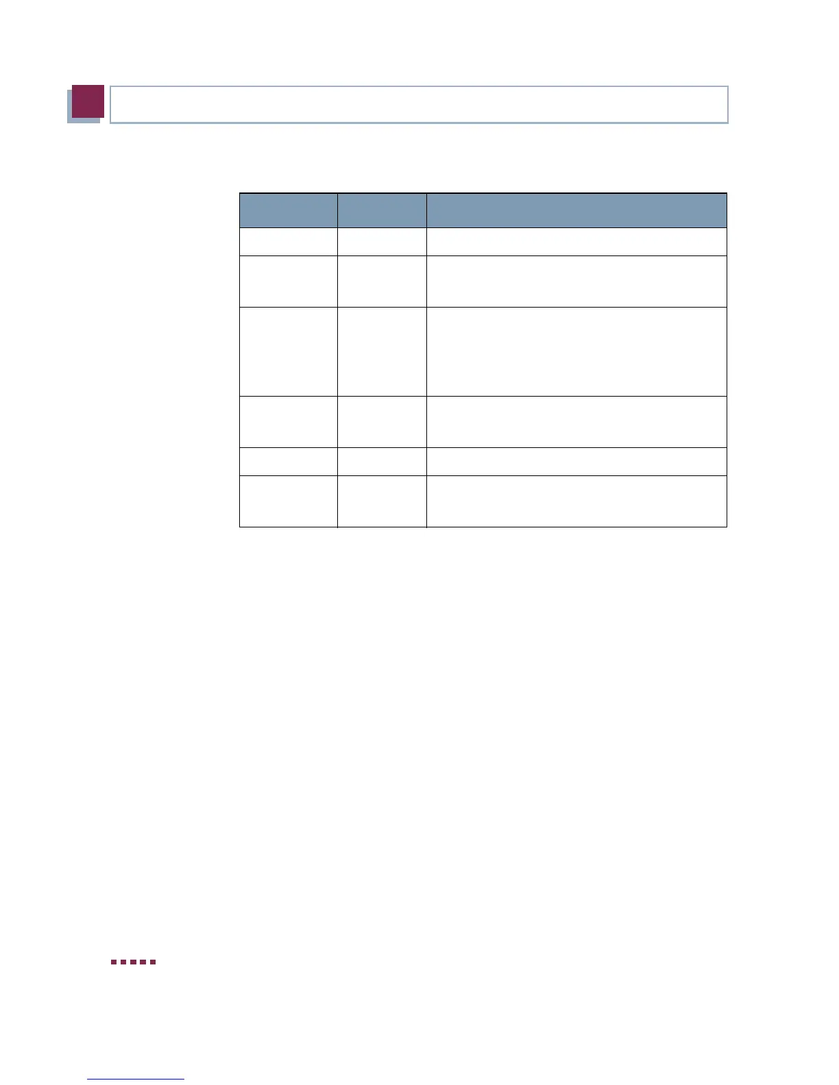
In operational mode the LEDs display the following status information:
Table 3-2: LED status display
3.4 Connections
All connections are located on the rear of the gateway. bintec R232b of-
fers a 4-port Ethernet switch, an ETH interface, an ISDN interface, an
ADSL interface as well as a serial interface.
LED Status Information
Power on Power supply has been connected.
Status on
flashing
The gateway is booting.
The gateway is active.
1 to 4 on
flashing
The gateway is connected to the Ethernet
(100 Mbit/s or 10 Mbit/s respectively).
Data traffic via the Ethernet interface (100
Mbit/s or 10 Mbit/s respectively).
ETH on
flashing
The gateway is connected to the Ethernet.
Data traffic via the Ethernet interface.
ADSL on ADSL connection is active.
ISDN on
flashing
One B-channel is used.
Both B-channels are used.
 Loading...
