6 bintec User’s Guide Technical Data
1
bintec R230a
Table 1-2: LED status display
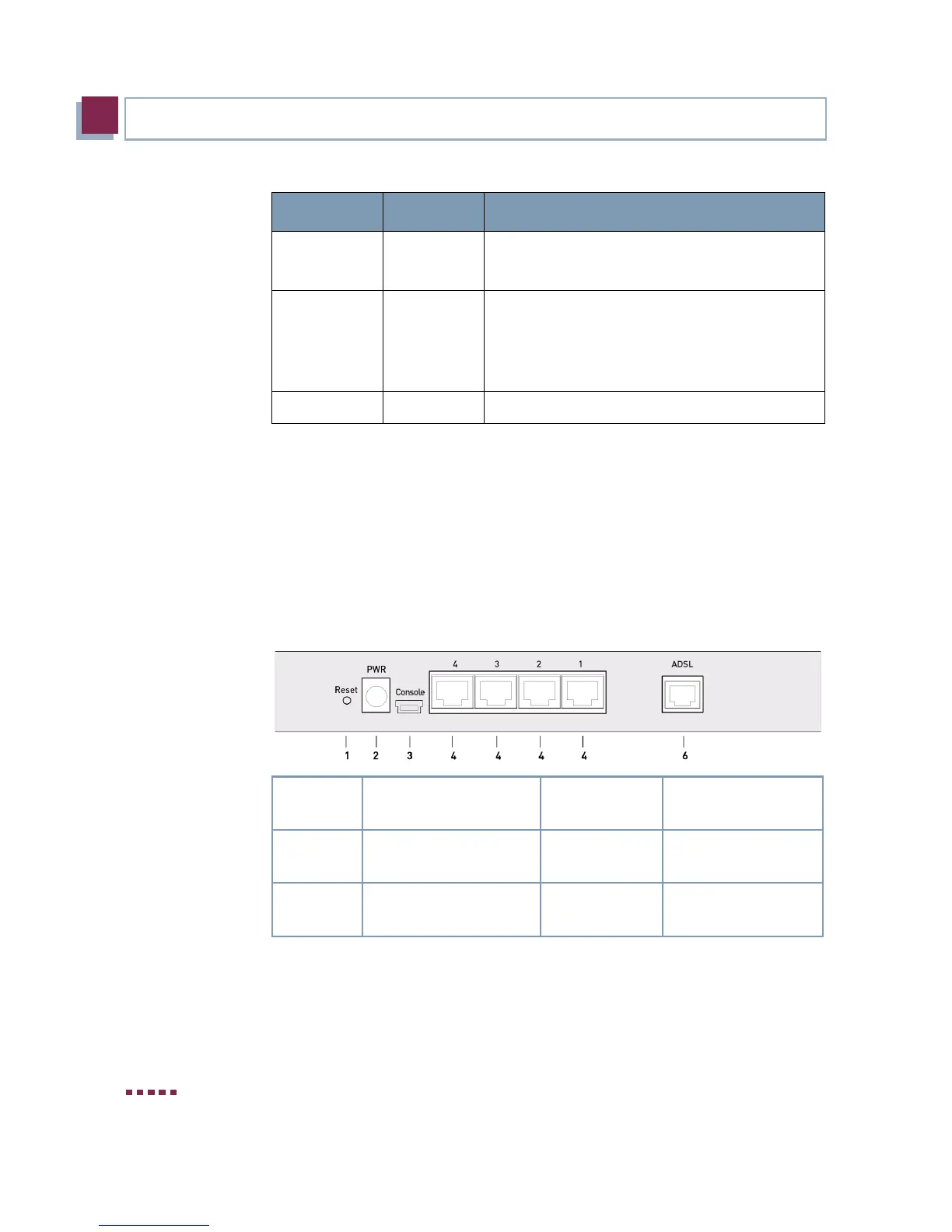
1.4 Connections
All connections are located on the rear of the gateway. bintec R230a offers
a 4-port Ethernet switch, an ADSL interface as well as a serial interface.
The connections are arranged as follows:
Figure 1-2: bintec R230a rear
Status on
flashing
The gateway is booting.
The gateway is active.
1 to 4 on
flashing
The gateway is connected to the Ethernet
(100 Mbit/s or 10 Mbit/s respectively).
Data traffic via the Ethernet interface (100
Mbit/s or 10 Mbit/s respectively).
ADSL on ADSL connection is active.
1. Reset Reset Button 4.
4/3/2/1
10/100 Base-T Eth-
ernet interface
2.
PWR
Socket for power sup-
ply
6. ADSL ADSL interface
3.
Console
Serial interface
LED Status Information
 Loading...
