Technical Data bintec User’s Guide 33
4
Connections
Table 4-2: LED status display
4.4 Connections
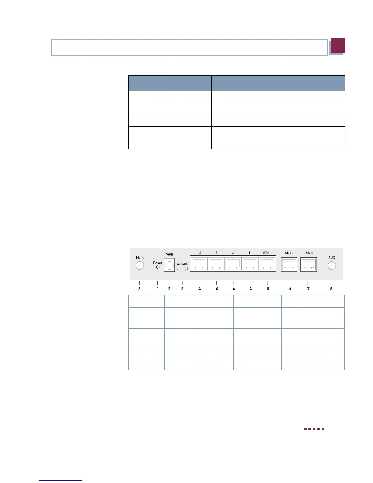
All connections are located on the rear of the gateway. bintec R232bw of-
fers a 4-port Ethernet switch, an ETH interface, an ISDN interface, an
ADSL interface as well as a serial interface.
The connections are arranged as follows:
Figure 4-2: bintec R232bw rear
ETH on
flashing
The gateway is connected to the Ethernet.
Data traffic via the Ethernet interface.
ADSL on ADSL connection is active.
ISDN on
flashing
One B-channel is used.
Both B-channels are used.
1. Reset Reset Button 5. ETH Ethernet interface
2.
PWR
Socket for power sup-
ply
6. ADSL ADSL interface
3.
Console
Serial interface 7. ISDN ISDN interface
4.
4/3/2/1
10/100 Base-T Ether-
net interface
8. RSMA connection
LED Status Information
 Loading...
