● To install the unit it is necessary to create openings in
the floor. The openings in the floor of the vehicle must be
accessible and, therefore, must not be covered by parts
of the chassis frame behind or the like.
● These openings must not be reached by splashes from
the wheels; fit a splash guard or something similar if
necessary.
● Take care to leave a gap of at least 1⁄”(30mm) between
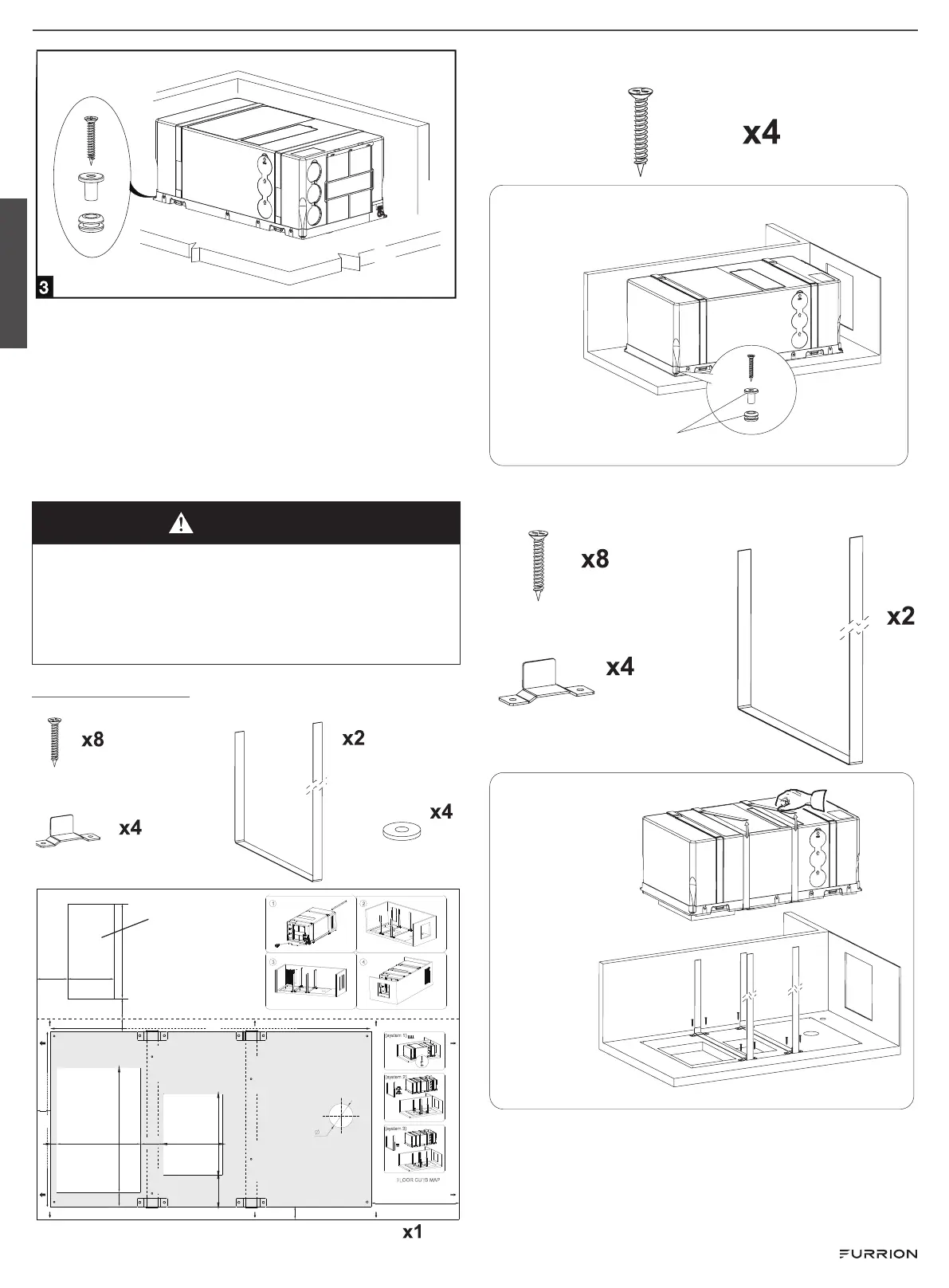
the unit and any adjacent wall. Secure the unit to the floor
using the kit provided.
WARNING
The unit must be installed leveled. Maximum allowed angle
is 10° to prevent condensing water to enter the coach
interiors. Before making the holes, always check there are
no cables, gas pipes, parts of the chassis frame or the like
underneath or hidden. Seal the machined surfaces of the
openings in the floor with water-repellent sealants.
Mounting options:
Parts supplied for the air-conditioner installation.
(system 1)
(system 2)
(system 3)
FLOOR CUTS MAP
51.8
31.9
71.8
16
55
DRAIN HOLE
FIXING HOLE
(system 1)
FIXING HOLE
(system 1)
FIXING HOLE
(system 1)
FIXING HOLE
(system 1)
FRONT
FIXING HOLE
(system 2)
FIXING HOLE
(system 2)
FIXING HOLE
(system 2)
FIXING HOLE
(system 2)
FIXINGHOLE
(system3)
FIXINGHOLE
(system3)
FIXINGHOLE
(system3)
FIXINGHOLE
(system3)
INLET
68 .2
191
2
135.4
184.4
OUTLET
HB9000
734
398
KEEP THIS DISTANCE BETWEEN THE UNIT AND THE SURROUNDING WALLS
10670.5
216
46
30
30
200
30
TO THE SIDE OF THE EXTERIOR WALL
1 2
3 4
(to optimize the performance of the unit)
Installation:
1.Open the side cover EPP,and have the
foam sticked around the air outlet.
2.Make a whole of the indicated size in
proper position.
3.Fix the grille.
4.Have the unit installed.
(Pls check when installation foam
thickness decided)
Hole as an option
Option 1: Use 4 screws(ST4.0*35mm) to bolt unit to the floor
using the built in grommets and spacers.
Option 2: Mount the brackets to the floor by using the
supplied 8 screws(ST4.0*35mm). Pull through the belts as
shown and tighten them.
English
Rev: 12-21-23
- 7 -
 Loading...