EasyManua.ls Logo

Furuno BR-500 - User Manual

Furuno BR-500
93 pages
To Next Page IconTo Next Page
Loading...
BRIDGE NAVIGATIONAL WATCH
ALARM SYSTEM (BNWAS)
BR-500
OPERATOR'S MANUAL
www.furuno.com
Model

Table of Contents

Other manuals for Furuno BR-500

Questions and Answers:

Furuno BR-500 Specifications

General IconGeneral
BrandFuruno
ModelBR-500
CategorySecurity System
LanguageEnglish

Summary

Important Notices

Product Disposal

Instructions for discarding the product according to local regulations.

Used Battery Disposal

Guidelines for battery disposal, including EU and USA regulations.

Safety Instructions

Warning Label Information

Details about the warning label attached to the processor unit.

Foreword

System Features

Overview of the BR-500's capabilities and compliance with standards.

Software History

Details on software versions for the Main Alarm Panel and Processor Unit.

Usage Precautions

Precautions for back-up power supply and motion detector usage.

Motion Detector (BR-560)

Details on motion detection principles and potential mis-detection.

Resetting the Watch Alarm Timer

Procedure for resetting the watch alarm timer using the Timer Reset Panel.

System Configuration

Main Alarm Panel (BR-510)

Main Alarm Panel Controls

Description of buttons and their functions on the Main Alarm Panel.

System Power On;Off

Procedure for turning the BNWAS system on and off.

BNWAS Display Overview

Explanation of the different areas and indicators on the BNWAS display.

Adjusting Display and Key Backlighting

How to adjust the LCD/LED brilliance and key backlighting.

Assigning Backup Officers

Procedure for assigning up to six backup officers to the system.

Operating Modes

Description of the three main operating modes: Manual OFF, Manual ON, AUTO.

Dormant Period Setting

Information on setting the watch time interval in the Administrator Menu.

Watch Alarm Sequence

Explanation of how the watch alarm checks for OOW presence and triggers alerts.

Help Area and Alerts

How the help area displays system failures, operational events, and alerts.

System Failure Indications

Describes how system failures are indicated and the operation flow.

Active Alert List and Alert Log

How to access and view the active alert list and alert log.

Operational Event Indications

How the Main Alarm Panel displays messages for operational events.

Making an Emergency Call

Procedure to immediately start the watch timer from the 2nd stage.

Calling a Navigation Officer

How to use the call feature to contact a backup officer.

External Emergency Call (Backup Navigator)

Receiving external emergency calls and system behavior.

Optional Equipment

Timer Reset Panels (BR-530, BR-550)

Description and operation of the Timer Reset Panels.

Cabin Panel (BR-540)

Installation and function of the Cabin Panel for alarms and status.

Motion Detector (BR-560)

Detection method, range, and function of the motion detector.

Flash Beacon (BR-570)

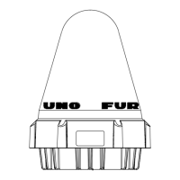
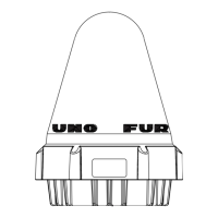
Function and operation of the Flash Beacon during alarm stages.

Maintenance and Troubleshooting

Routine Maintenance

Guidelines for monthly maintenance checks of the equipment.

Fuse Replacement

Instructions for replacing fuses in the Processor Unit PWR Board.

Troubleshooting Common Issues

Table of common problems and their remedies for the system.

Connection Check Procedure

Procedure to test connections between the Processor Unit and panels.

Major Parts Life Expectancy

Information on the expected life of major parts, specifically the fan.

Installation

Equipment Lists

Lists of standard and optional equipment supplied with the BNWAS.

Mounting Considerations

Guidelines for installing units in compliance with standards and optimal placement.

Main Alarm Panel (BR-510) Mounting

Instructions for desktop and flush mounting the Main Alarm Panel.

Shield Film Installation

How to install the shield film to reduce display brilliance.

Processor Unit (BR-520) Mounting

Mounting instructions for the Processor Unit on a bulkhead or deck.

Optional Units Mounting

Flush mounting instructions for Timer Reset, Cabin, Motion Detector, and Flash Beacon.

Wiring Instructions

General wiring procedures for the Processor Unit.

Cable Fabrication and Fixing

Steps for fabricating and securing cables for the Processor Unit.

Wiring Information Details

Wiring information for Operator fitness, cables, motion detector, and input ports.

Main Alarm Panel Wiring

Connecting the Processor Unit to the Main Alarm Panel.

Wiring for Optional Units

Wiring procedures for Timer Reset, Cabin Panel, Motion Detector, Flash Beacon.

Optional Unit Cable Fabrication

How to fabricate cables for Cabin Panel, Timer Reset, Flash Beacon, and Motion Detector.

DIP and Rotary Switch Settings

Location and function of DIP and Rotary switches in the Processor Unit.

Adjusting LED Brilliance

How to adjust the brilliance of LEDs on various panels.

Menu Settings

Overview of menu settings for system configuration.

Administrator Menu

Initial system settings accessible through the Administrator Menu.

Performing Self Test

Procedure for checking equipment operation using the Self TEST function.

Changing the Password

Steps to change the administration password.

Resetting Password to Factory Default

Procedure to reset the administration password to its factory default.

Service Menu

Menu items for installers and service technicians, including system test and alarm modes.

Restoring Factory Settings

Procedure to restore all system default settings.

I;O Sentence Information

Communication specifications and details on input/output sentences.

Input Sentence Details

Explanation of ACK input sentences and their meanings.

ACN Alert Command

Format and meaning of the ACN alert command sentence.

EVE General Event Message

Format and meaning of the EVE general event message.

HBT Heartbeat Supervision Sentence

Format and meaning of the HBT heartbeat supervision sentence.

Output Sentence Details

Explanation of ALC, ALF, ARC, HBT, PFEC output sentences.

ALF Alert Sentence

Format and meaning of the ALF alert sentence.

ARC Alert Command Refused

Format and meaning of the ARC alert command refused sentence.

ALR Alarm Sentence

Format and meaning of the ALR alarm sentence, including alarm modes.

HBT Heartbeat Supervision Sentence Details

Details on the HBT heartbeat supervision sentence and proprietary output sentences.

Appendices and Guides

Menu Tree and Settings

Overview of menu structure for Administrator and Service menus.

Abbreviations Used

List of abbreviations and their meanings used in the manual.

JIS Cable Guide

Guide to identifying JIS cables and their specifications.

Alert Icons, IDs, Meanings, and Measures

Alert Icons and Attributes

Description of alert icons, priority levels, statuses, and audible alerts.

Legacy Mode Alerts

Information on legacy mode alerts, IDs, meanings, and measures.

Alertl;F1 and Alertl;F2 Mode Alerts

Details on alerts, IDs, meanings, and measures for Alertl/F1 and Alertl/F2 modes.

Specifications

Main Alarm Panel (BR-510) Specifications

Display, brilliance, status indication, and functions of the Main Alarm Panel.

Processor Unit (BR-520) Specifications

Input/output ports, serial signals, and data sentences for the Processor Unit.

Cabin Panel (BR-540) Specifications

Input voltage, visible indication, audible alarm, and controls for the Cabin Panel.

Timer Reset Panels (BR-530;BR-550) Specifications

Visible indication, audible alarm, and controls for Timer Reset Panels.

Motion Detector (BR-560) Specifications

Detection method, distance, temperature gap, angle, and object size.

Flash Beacon (BR-570) Specifications

Function and operation of the Flash Beacon during alarm stages.

Power Source Specifications

Details on AC and DC power requirements for the BNWAS system.

Environmental Conditions

Ambient temperature, humidity, degree of protection, and vibration ratings.

Coating Color Specifications

Color specifications for watertight timer reset panel and others.

Packing List

Packing List for BR-510

List of items included in the BR-510 package.

Packing List for BR-520

List of items included in the BR-520 package.

Packing List for BR-520 (10 m Cable)

List of items for BR-520 with 10m cable.

Packing List for BR-520 (N Cable)

List of items for BR-520 with N cable.

Packing List for BR-510;520 (E-10)

List of items for BR-510/520 with E-10 configuration.

Packing List for BR-510;520 (E-N)

List of items for BR-510/520 with E-N configuration.

Outline Drawings and Dimensions

Main Alarm Panel Tabletop Mount Outline

Dimensional drawing for tabletop mounting the Main Alarm Panel.

Main Alarm Panel Flush Mount Outline

Dimensional drawing for flush mounting the Main Alarm Panel.

Processor Unit Bulkhead Mount Outline

Dimensional drawing for bulkhead mounting the Processor Unit.

Timer Reset Panel Flush Mount Outline

Dimensional drawing for flush mounting the Timer Reset Panel.

Timer Reset Panel Bulkhead Mount Outline

Dimensional drawing for bulkhead mounting the Timer Reset Panel.

Watertight Timer Reset Panel Flush Mount Outline

Dimensional drawing for flush mounting the Watertight Timer Reset Panel.

Watertight Timer Reset Panel Bulkhead Mount Outline

Dimensional drawing for bulkhead mounting the Watertight Timer Reset Panel.

Motion Detector Flush Mount Outline (Alternative)

Dimensional drawing for flush mounting the Motion Detector (alternative view).

Cabin Panel Flush Mount Outline

Dimensional drawing for flush mounting the Cabin Panel.

Cabin Panel Bulkhead Mount Outline

Dimensional drawing for bulkhead mounting the Cabin Panel.

Cabin Panel Flush Mount Outline (Alternative)

Dimensional drawing for flush mounting the Cabin Panel (alternative view).

Cabin Panel Bulkhead Mount Outline (Alternative)

Dimensional drawing for bulkhead mounting the Cabin Panel (alternative view).

Motion Detector Flush Mount Outline (Alternative)

Dimensional drawing for flush mounting the Motion Detector (alternative view).

Motion Detector Bulkhead Mount Outline (Alternative)

Dimensional drawing for bulkhead mounting the Motion Detector (alternative view).

Motion Detector Flush Mount Outline (Another Alternative)

Dimensional drawing for flush mounting the Motion Detector (another alternative view).

Motion Detector Bulkhead Mount Outline (Another Alternative)

Dimensional drawing for bulkhead mounting the Motion Detector (another alternative view).

Flash Beacon Flush Mount Outline

Dimensional drawing for flush mounting the Flash Beacon.

Flash Beacon Bulkhead Mount Outline

Dimensional drawing for bulkhead mounting the Flash Beacon.

Flash Beacon Flush Mount Outline (Alternative)

Dimensional drawing for flush mounting the Flash Beacon (alternative view).

Interconnection Diagram

Declaration of Conformity

Related product manuals