The provided manual describes the FURUNO Ship Security Alert System (SSAS), specifically for use with the Inmarsat-C MES FELCOM 15 or FELCOM 16. This system is designed to meet SOLAS Resolution XI-2/6 requirements for vessels of 500 GT or more constructed before July 1, 2004, mandating the installation of an SSAS.
Function Description
The primary function of the SSAS is to alert specified addresses (e.g., the ship's company or management company) that the vessel is under attack by intruders. When activated, the SSAS transmits a report containing the ship's name, MMSI number, position, and other relevant information to up to five pre-defined locations. A critical feature of this system is that no audible or visible alarm is generated on board the ship during transmission, preventing intruders from discovering the alert.
The system is protected by a password to ensure that only authorized personnel, such as the ship's captain, can set up or test the SSAS.
Important Technical Specifications
The SSAS consists of several units, including:
- Antenna Unit (IC-115 for FELCOM 15, IC-116 for FELCOM 16): Exposed to weather.
- Terminal Unit (IC-215 for FELCOM 15): Protected from weather.
- Communication Unit (IC-216 for FELCOM 16): With internal GPS receiver, protected from weather.
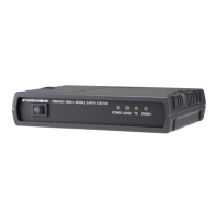
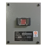
- Junction Box (IC-315): Required for FELCOM 16 installations, already integrated into FELCOM 15. Protected from weather.
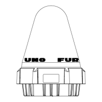
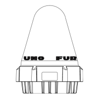
- SSAS Alert Unit (IC-307): Up to three units can be connected. Protected from weather.
Power Supply:
- 100/115/220/230 VAC, 1Ø, 50/60 Hz (via AC-DC Power Supply PR-240-CE).
- 12/24 VDC (for 12 VDC, a DC-DC converter is required for the PP-510 printer).
- Any AC-DC power supply fulfilling IEC 60945 requirements may be used.
Compass Safe Distances for Junction Box (IC-315):
- Standard compass: 1.0 m
- Steering compass: 0.7 m
Compass Safe Distances for SSAS Alert Unit (IC-307):
- Standard compass: 0.70 m
- Steering compass: 0.45 m
Cable Specifications for Junction Box (IC-315) to SSAS Alert Unit (IC-307):
- JIS cable TTYCS-4 or CO-SPEVV-SB-C 0.2x5P.
- Maximum total cable length: 200 m.
- TTYCS-4 cable sectional view:
- Diameter: 16.3 mm
- Conductor: S = 0.75 mm², Diameter = 1.11 mm
- Includes armor, sheath, and shield.
Usage Features
Operation Modes:
- Normal mode: Displays menus other than SSAS-related ones.
- SSAS manager mode: Activated by a password. This mode allows access to all SSAS-related menus and enables cancellation of SSAS report transmission. The equipment always starts in normal mode.
SSAS Activation:
- Open the cover of the SSAS alert button.
- Press the latch-type button (hit and release to activate).
- If addresses are preset, the SSAS report is sent to one address 30 seconds after activation (up to 5 addresses).
- An LES (Land Earth Station) sends an acknowledgment to the ship.
- For multiple addressees, steps 3 and 4 are repeated.
- Continuous transmission of the SSAS report begins, with a user-specified interval.
- To stop transmission, the button must be pressed again to deactivate it (only possible in SSAS manager mode).
Cancellation of Transmission:
- If the button is accidentally pressed, transmission can be canceled by pressing it again within 30 seconds of the initial press. The button will pop out, and the message "INF: SSAS UNIT activation has been canceled." will appear. For FELCOM 16, the POWER lamp will flash for 30 seconds.
- Repeated transmission can be canceled from either operating mode by pushing the button OFF→ON→OFF→ON→OFF, ensuring no more than three seconds elapse between pushes.
- Repeated transmission cannot be canceled by turning off the unit; it will resume when powered on again.
SSAS Report Content:
- Includes Vessel Name, MMSI, IMN, position (LAT/LON), time, course, speed, and a "Help me!" message.
- Additional "Other Inf." (three lines) can be manually entered.
Password Protection:
- The system uses a password ("ship security alert" by default) to access the SSAS manager mode and change settings. The password must be at least six characters long.
Maintenance Features
Installation and Mounting:
- The junction box (IC-315) and SSAS alert unit (IC-307) require specific mounting procedures, including securing with self-tapping screws.
- Cables are connected to terminal boards inside the units. For the SSAS alert unit, cables can be led in from the bottom or rear panel, with adjustable clamp orientation.
- Flush mounting is possible with an optional kit (OP16-28).
Wiring:
- Detailed wiring diagrams are provided for connecting the SSAS alert units to the junction box and the junction box to the communication unit (FELCOM 16).
- Jumper block settings on the SSAS ALERT Board (16P0229) must be adjusted according to the number of SSAS units installed (up to three).
Initial Settings:
- SSAS functions are enabled through the "Command Window" in the System Setup menu, requiring a "furunoservice" job number and a password.
Testing the Button:
- The SSAS buttons can be tested in SSAS manager mode without transmitting an actual SSAS report.
- The test mode displays messages like "Distress/SSAS buttons are under test mode." and "SSAS UNIT works correctly."
- During the test, an SSAS test report is automatically sent to the youngest SSAS report number's address 30 seconds after the button is pushed (unless canceled).
- The ERROR LED flashes if the button stays on for more than 10 seconds or when switching to normal mode after a test.
SSAS Report Test:
- A test report can be transmitted to a specified address without using the button.
- The test report message states "!!! Test Call !!!" to indicate it's a test.
- After transmission, the "Status" for that report is automatically set to ON.
Backup:
- SSAS report settings can be saved to a floppy disk for backup purposes.
Automatic Reset:
- The normal mode is automatically restored after 60 minutes in test mode.