Do you have a question about the Furuno FAR-2835S and is the answer not in the manual?
Describes hazardous voltage and risks of serious injury or death.
Warns about harmful RF energy emitted by the radar antenna.
Safety procedures for servicing antenna unit and mains switchboard.
CAUTION regarding proper grounding and correct fuse selection.
Detailed list of components included in the complete radar set.
List of optional accessories and their specifications.
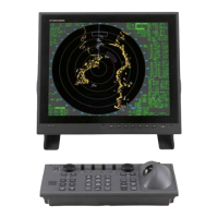
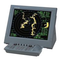
Illustrates general layouts and dimensions of system components.
Shows internal circuit diagrams for the radar system.
Step-by-step guide for assembling the radar antenna radiator.
Requirements for designing antenna unit support structures.
Siting considerations for mounting the antenna unit.
Procedure and diagrams for safely lifting the antenna unit.
Detailed steps for mounting the scanner unit to a platform or deck.
Diagram illustrating the installation of the scanner unit.
Considerations for mounting the display unit on a tabletop or pedestal.
Steps for mounting the display unit on a tabletop or pedestal.
Instructions for connecting and mounting the separate control panel.
Procedure for fabricating antenna cables for the unit.
Fabricating power cables and leading cables to the display unit.
Connecting power cable and gyro signal to the display unit.
Procedure for grounding the display unit to prevent interference.
Circuit diagram for the INT Board's signal input/output.
Table detailing input and output signals on the INT Board.
Diagram showing connector locations on the INT Board.
Instructions for grounding cables and covering unused slots.
Procedure to change the radar's power specifications (100V/220V AC).
Wiring information and thermal relay ratings for the PSU-004.
How to access and operate the radar's initialization menus.
Procedure to reset the radar to factory default settings.
Procedure to compensate for heading error.
Adjusting sweep timing based on signal cable length.
Adjusting video amplifier input level for long signal cables.
Procedure to suppress main bang on the radar screen.
Confirming automatic and manual tuning of the radar receiver.
Procedure to confirm magnetron heater voltage.
Description of the various initial setting menus.
Guide to setting up the radar's four function keys.
Step-by-step instructions for setting function keys.
Diagram of the radar's initialization and adjustment menu structure.
A checklist to ensure all installation steps are completed.
Procedure for adjusting the ARP Board.
General procedure for installing the GYRO CONVERTER Board.
Connecting an external power supply to the GYRO CONVERTER Board.
Flowchart to confirm gyrocompass specifications.
Setting DIP switches and jumpers by gyrocompass specifications.
Settings table for various gyrocompass makes and models.
Diagram showing location of DIP switches and jumper wires.
Procedure for setting bearing on the radar display.
Lists signal cable assemblies and flat cable assemblies.
Lists crimp-on lugs, NH connector parts, and lugs.
Lists nuts, bolts, washers, and panel/supporting plates.
Lists key labels, name plates, and unit covers.
Lists spare fuses for the radar system.
Diagram showing dimensions for tabletop display unit.
Diagram showing dimensions for tabletop display unit without keyboard.
Diagram showing dimensions for the control unit.
Diagram showing dimensions for console display unit.
Diagram showing dimensions for the power supply unit.
Diagram showing dimensions and mounting details for scanner unit.
Additional dimensional details for the scanner unit.
Shows overall system connections between units.
Schematic diagram for the antenna unit.
Schematic diagram for the power supply unit.
| Brand | Furuno |
|---|---|
| Model | FAR-2835S |
| Category | Marine Radar |
| Language | English |