Do you have a question about the Furuno FAR-2827 and is the answer not in the manual?
Lists the specific radar models covered by this manual, including FAR-2117, FAR-2817, FAR-2827W, and FAR-2837SW.
Details updates to the radar program, including list of programs, factory modifications, and specific changes for SPU and RFC versions.
Lists the problems eliminated for SPU software version 2.22, covering issues like keyboard lock-ups and display overlays.
Details the bug fixes for RFC software version 1.20, including issues with tuning search and check sum data.
Details the necessary parts and modification procedure for the 12 kW and 25 kW X-band radar.
Outlines the necessary parts and modification procedures for the 30 kW TR UP radar.
Details the necessary parts and modification procedures for the 30 kW TR DOWN radar.
Describes the symptom of no picture appearing on the screen, often occurring upon restarting.
Provides the solution to the 'No Picture' issue, involving replacing the DVI I/F board or removing diodes.
Provides a general overview of the radar system, including its components and interconnections.
Details the system configuration table, listing various components and their compatibility.
Provides detailed technical specifications for TR units, antenna radiators, monitors, and power consumption.
Lists and describes the various functions available on the radar system.
Details the RPU-013 processor unit, including its views, ports, and internal boards.
Describes the scanner unit for different radar models like FAR-2xx7, FAR-2827W, FAR-2837S, and FAR-2837SW.
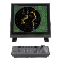
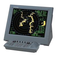
Details the specifications and block diagrams of MU-201CR and MU-231CR monitor units.
Describes the standard control units RCU-014, RCU-015, and RCU-016, including their features.
Details optional units such as the CU-200 card interface and HUB-100 switching hub.
Describes the standard and slim type radar consoles, including their dimensions and connection points.
Explains how to access the operational menu by pressing specific key combinations.
Provides a critical warning about power cycling after settings changes to ensure data is saved.
Details the process for changing IP addresses and restarting units connected to the LAN.
Lists essential settings required after installation, including menus for Echo ADJ, Installation, and ANT Select.
Describes how to check the NMEA data interface by executing a TEST function.
Explains how to perform a loopback test to identify interface problems with gyro or NMEA data.
Details the process of updating programs via serial port connection with a PC.
Provides instructions for making LAN connections using cross or straight cables and explains HUB-100 Auto-MDIX.
Details connection procedures with ECDIS, including SERIAL and LAN settings.
Discusses RPU-013 compatibility with X-band, S-band, and differences in PWR and HV-TX boards.
Provides a general overview of the system configuration, including components and their communication methods.
Shows examples of system configurations for different radar models like FAR-2127 and FAR-2827.
Explains the inter-switch function for connecting multiple radars via LAN, allowing control and data sharing.
Details the system configuration table, listing various components and their compatibility across different radar models.
Provides detailed technical specifications for TR units, antenna radiators, and monitor units.
Details the RPU-013 processor unit, including its views, ports, and internal boards like SPU, NET-100, and PWR.
Describes the scanner unit for different radar models, including FAR-2xx7, FAR-2827W, FAR-2837S, and FAR-2827SW.
Details the specifications and block diagrams of monitor units MU-201CR and MU-231CR.
Describes the standard control units RCU-014, RCU-015, and RCU-016, including their features and connections.
Details optional units such as the CU-200 card interface and HUB-100 switching hub.
Describes the standard and slim type radar consoles, including dimensions and internal components.
Lists and explains optional menus available for system configuration.
Provides an overview of the factory menu settings and their functions.
Explains the initialize menu, its parameters, and their related page references.
Details various initialization settings for the system, including cable attenuation, timing, and model settings.
Explains jumper settings for AIS and HDG ports on the terminal board.
Explains how to set the S1 switch on the SPU board based on the connected monitor type.
Details settings for AD-100 or GC-10 for AD and NMEA data input, including factory settings.
Explains how to change IP addresses for CU-200 units connected to the network.
Details how to select NAV DATA input sources like GPS1, GPS2, LAN, or Dead Reckoning.
Explains how to access the operational menu by pressing specific key combinations.
Provides a critical warning about power cycling after settings changes to ensure data is saved.
Details the process for changing IP addresses and restarting units connected to the LAN.
Lists essential settings required after installation, including menus for Echo ADJ, Installation, and ANT Select.
Describes how to check the NMEA data interface by executing a TEST function.
Explains how to perform a loopback test to identify interface problems with gyro or NMEA data.
Guides on checking for EPFS, GYRO, and other errors.
Details the process of updating programs via serial port connection with a PC.
Explains how to connect a sub monitor and the video signal output.
Provides instructions for making LAN connections using cross or straight cables and explains HUB-100 Auto-MDIX.
Details connection procedures with ECDIS, including SERIAL and LAN settings.
Discusses RPU-013 compatibility with X-band, S-band, and differences in PWR and HV-TX boards.
Provides a general overview of the system configuration, including components and their communication methods.
Shows examples of system configurations for different radar models like FAR-2127 and FAR-2827.
Explains the inter-switch function for connecting multiple radars via LAN, allowing control and data sharing.
Details the system configuration table, listing various components and their compatibility across different radar models.
Provides detailed technical specifications for TR units, antenna radiators, and monitor units.
Details the RPU-013 processor unit, including its views, ports, and internal boards like SPU, NET-100, and PWR.
Describes the scanner unit for different radar models like FAR-2xx7, FAR-2827W, FAR-2837S, and FAR-2837SW.
Details the specifications and block diagrams of monitor units MU-201CR and MU-231CR.
Describes the standard control units RCU-014, RCU-015, and RCU-016, including their features and connections.
Details optional units like the CU-200 card interface and HUB-100 switching hub.
Describes the standard and slim type radar consoles, including dimensions and internal components.
Lists and explains optional menus available for system configuration.
Provides an overview of the factory menu settings and their functions.
Explains the initialize menu, its parameters, and their related page references.
Details various initialization settings for the system, including cable attenuation, timing, and model settings.
Explains jumper settings for AIS and HDG ports on the terminal board.
Explains how to set the S1 switch on the SPU board based on the connected monitor type.
Details settings for AD-100 or GC-10 for AD and NMEA data input, including factory settings.
Explains how to change IP addresses for CU-200 units connected to the network.
Details how to select NAV DATA input sources like GPS1, GPS2, LAN, or Dead Reckoning.
Explains how to access the operational menu by pressing specific key combinations.
Provides a critical warning about power cycling after settings changes to ensure data is saved.
Details the process for changing IP addresses and restarting units connected to the LAN.
Lists essential settings required after installation, including menus for Echo ADJ, Installation, and ANT Select.
Describes how to check the NMEA data interface by executing a TEST function.
Explains how to perform a loopback test to identify interface problems with gyro or NMEA data.
Details the process of updating programs via serial port connection with a PC.
Provides instructions for making LAN connections using cross or straight cables and explains HUB-100 Auto-MDIX.
Details connection procedures with ECDIS, including SERIAL and LAN settings.
Discusses RPU-013 compatibility with X-band, S-band, and differences in PWR and HV-TX boards.
| Brand | Furuno |
|---|---|
| Model | FAR-2827 |
| Category | Marine Radar |
| Language | English |