www.furuno.com
All brand and product names are trademarks, registered trademarks or service marks of their respective holders.
Installation Manual
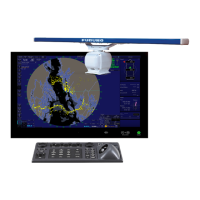
CHART RADAR
Model FAR-3230S(-BB)/FAR-3330S
(Product Name: MARINE RADAR)
SAFETY INSTRUCTIONS ................................................................................................ i
SYSTEM CONFIGURATION .......................................................................................... iii
EQUIPMENT LISTS........................................................................................................ vi
1. INSTALLATION.......................................................................................................1-1
1.1 Antenna Unit ......................................................................................................................1-1
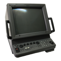
1.2 Monitor Unit........................................................................................................................1-8
1.3 Radar Control Unit, Trackball Control Unit.........................................................................1-8
1.4 Power Supply Unit (PSU-014/PSU-015)..........................................................................1-11
1.5 Processor Unit .................................................................................................................1-12
1.6 Sensor Adapter MC-3000S/3010A/3020D/3030D (option)..............................................1-13
1.7 Intelligent Hub HUB-3000 (option)...................................................................................1-14
1.8 Switching Hub HUB-100 (option).....................................................................................1-16
2. WIRING....................................................................................................................2-1
2.1 Overview ............................................................................................................................2-1
2.2 Antenna Unit ......................................................................................................................2-3
2.3 Processor Unit .................................................................................................................2-10
2.4 Power Supply Unit ...........................................................................................................2-21
2.5 Monitor Unit......................................................................................................................2-25
2.6 Sensor Adapters (option).................................................................................................2-26
2.7 LAN Signal Converter Kit (option)....................................................................................2-43
2.8 Intelligent Hub HUB-3000 (option)...................................................................................2-47
2.9 How to Extend the Control Unit Cable (option) ................................................................2-48
3. SETTINGS AND ADJUSTMENTS ..........................................................................3-1
3.1 How to Access the Radar Installation Menu ......................................................................3-1
3.2 How to Align the Heading ..................................................................................................3-1
3.3 How to Adjust the Sweep Timing.......................................................................................3-2
3.4 How to Suppress Main Bang .............................................................................................3-3
3.5 Dual Radar Display............................................................................................................3-3
3.6 Other Settings....................................................................................................................3-6
4. INPUT/OUTPUT DATA............................................................................................4-1
4.1 Processor Unit ...................................................................................................................4-1
4.2 IEC 61162 Sentences........................................................................................................4-2
APPENDIX 1 JIS CABLE GUIDE .............................................................................AP-1
APPENDIX 2 ROD TERMINALS ..............................................................................AP-2
APPENDIX 3 DIGITAL INTERFACE ........................................................................AP-7
PACKING LISTS ......................................................................................................... A-1
OUTLINE DRAWINGS ................................................................................................ D-1
INTERCONNECTION DIAGRAMS.............................................................................. S-1