Do you have a question about the Furuno FAR-3320W and is the answer not in the manual?
General information and user responsibilities regarding the manual and equipment.
Instructions for proper disposal of the product according to local regulations.
Guidance on disposing of used batteries, emphasizing terminal protection.
Warning about harmful electromagnetic radio frequency energy emitted by the radar antenna.
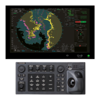
Overview of the key features of the FAR-3xx0 series marine radar.
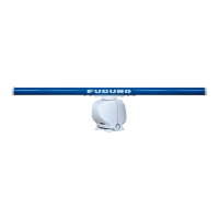
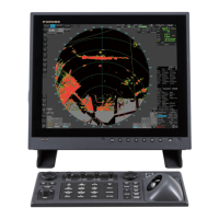
Details the components of the system, including control and processor units.
Step-by-step instructions for powering the radar system on and off.
Guide to choosing display color palettes to match ambient lighting conditions.
Instructions for adjusting the display brilliance using the BRILL control or InstantAccess knob.
Overview of the available operating modes: RADAR and CHART for RADAR.
Describes the layout of display screens including operational buttons, boxes, and indications.
Explains the Status bar at the top of the screen, its buttons, and indications.
Details the InstantAccess bar on the left edge of the screen for quick access to functions.
Describes the sensor information and datum box, including data indications and sensor states.
Explains the menu structure and basic operation procedures.
Explains context-sensitive menus available with buttons and boxes in radar mode.
Details the cursor position box and its displayed information.
Guide on selecting navigation sensors for radar and chart modes.
Instructions for entering own ship speed, including automatic or manual input.
Procedure for entering manual or automatic heading input.
Explains how to use the Man Overboard (MOB) feature to mark a position.
Procedure for offsetting position to compensate for errors affecting accuracy.
Guide to switching between UTC and local time formats and setting local time.
Instructions for capturing and saving screenshots from the display.
Overview of the Settings menu for accessing user profiles and system configurations.
How to create, disable, activate, and restore user profiles for customized settings.
Steps to view software version, system information, and the operator's manual.
Provides operational tips for the display area, InstantAccess bar, and Mark box.
Instructions on initiating radar transmission after the magnetron has warmed up.
Guide on adjusting the radar receiver for optimal tuning and reception.
Information on selecting and changing the radar pulse length for different range scales.
Steps for adjusting the radar receiver's sensitivity using the GAIN control or button.
Methods for reducing sea clutter using automatic or manual A/C SEA controls.
Techniques for reducing rain clutter using A/C RAIN control to improve target visibility.
How to activate the interference rejector to reduce mutual radar interference.
Explanation of the echo stretch feature for enlarging targets and its levels.
Describes the echo averaging feature for reducing sea clutter and improving target discrimination.
Details the ACE function for automatic detection and reduction of sea and rain clutter.
Instructions on using the noise rejector to reduce white noise and improve the signal-to-noise ratio.
Explanation of the wiper feature for reducing unwanted echoes and clearing the picture.
Guide on assigning function keys to provide optimum radar settings for specific situations.
Method to reject second-trace echoes that may appear as false echoes on the screen.
Overview of available presentation modes: Head-up, Course-up, North-up, True Motion, etc.
Instructions for selecting the radar range scale and range ring interval.
Methods for measuring target range using range rings, cursor, or VRM.
Procedure for measuring target bearing using EBLs and selecting bearing references.
Using offset EBL for measuring range/bearing and assessing collision risk.
Steps to measure range and bearing between multiple targets using EBL and VRM.
Procedure for off-centering the display to expand the view field without changing range scale.
How to display and manage target trails, including true/relative motion and trail time.
Guide on using PI lines for maintaining constant distance from coastlines or partner ship.
Instructions for using the zoom function to enlarge specific areas of interest on the display.
Details on displaying and managing various markers like heading line, stern marker, and own ship marker.
Adjusting the relative brilliance levels of various markers and readouts on the screen.
Setting up watch alerts for regular visual and aural reminders to monitor the radar picture.
Explains the information box contents, including navigation data and route information.
How the interswitch transfers radar signals between multiple monitor units in a network.
Information on enabling and operating the dual radar display function for B-type systems.
Activating and deactivating the performance monitor to check radar transmitter and receiver status.
Procedure for resetting the magnetron for antenna units after replacement.
Selecting and using the CCRP for referencing measurements and markers.
How to show, hide, inscribe, and erase drop marks for navigation points.
Setting up the anchor watch feature to monitor ship drift while at anchor.
Information on what a SART is and how the radar receives SART signals.
Explains the alert box, alert list, and how to manage alerts.
How to select the echo display area type, CIRCLE or WIDE.
Guide to selecting echo colors for display.
Procedure for rotating the antenna without transmission to prevent freezing.
Details on switching between radar and chart modes, and managing chart objects.
Explanation of minimum range, maximum range, bearing resolution, and false echoes.
Overview of the Target Tracking (TT) system and its compliance with IMO standards.
Instructions for displaying or hiding the TT mode indication and related options.
Guide on entering own ship's speed for TT and azimuth stabilized presentation modes.
How to enable automatic target acquisition and set acquisition zones.
Procedure for manually acquiring and tracking targets.
Steps to cancel tracking on individual or all targets.
Details on TT symbols, their default colors, names, and descriptions.
How to display target data for individual TTs and the TT pop-up information.
Explanation of vector display modes and their settings for own ship and targets.
How to enable/disable past position display and select past position reference.
Procedure for manually entering set and drift for accurate vector calculations.
Setting CPA and TCPA limits and managing the TT CPA/TCPA alarm.
How to enable/disable the TT lost target alert and set the lost target filter.
Simulating own ship's movement against tracked targets for maneuver planning.
Simulating collision risk using TT simulation mode and trial maneuver.
List of situations that trigger TT visual and audio alerts.
Factors affecting target tracking, including echo detection and quantization.
Discussion of factors like sea returns, rain, low clouds, and blind sectors affecting target tracking.
Steps to deactivate the AIS function, sleeping all AIS targets and messaging.
Instructions for displaying or hiding AIS targets on the radar display.
Details on various AIS symbols used for different target types and states.
Method to filter unnecessary sleeping AIS targets to declutter the screen.
Procedure for converting sleeping AIS targets to activated targets with course and speed vectors.
Instructions on how to sleep activated AIS targets to manage screen clutter.
How to display basic and expanded AIS target data by selecting the target.
Calculation of CPA/TCPA and management of AIS dangerous target alerts.
Adjusting the brilliance of AIS symbols on the display.
Selecting the color for AIS symbols.
How to enable/disable AIS lost target alerts and set the filter.
Displaying past position points for activated AIS targets.
Displaying AIS target vectors relative to ship's heading or North.
How to associate TT and AIS targets to avoid duplicate symbols.
Setting navigation status, ETA, destination, draught, and crew for voyage.
How to create, transmit, and display AIS messages.
Additional AIS features like ATON symbol color and scaled symbols.
Defines a radar map as a layer of marks and lines overlaid on the radar display for safety-related objects.
Lists available presentation modes for radar maps: North-up, Course-up, Head-up, etc.
Instructions for displaying or hiding the radar map on the radar display.
Procedure for entering marks and lines into the radar map, including selection, entry, and saving.
How to view the number of points used in each radar map file.
Steps to select and display a specific radar map file.
How to add comments to radar maps for identification and how to find existing comments.
Procedures for erasing individual marks/lines or those within a selected area.
Instructions for copying marks and lines between radar map files.
Steps to export radar maps to a USB flash memory.
Procedure for importing radar maps from another equipment via USB flash memory.
How to display or hide various radar map objects on the display.
Information on setting up and managing ship's track data.
How to show or hide the selected route and its elements on the radar display.
How to display active user charts on the radar display.
Description of the chart screen layout, including status bar, sensor info, and electronic chart area.
Procedure to select the operating mode, such as RADAR or CHART for RADAR.
Guide to selecting chart operating modes: Voyage navigation, Chart maintenance, or Voyage planning.
Instructions for changing the chart scale using buttons or scrollwheel.
How to select presentation modes like North up TM, Course up RM, etc., based on chart operating mode.
Details the cursor position box showing latitude, longitude, time to cursor, and bearing/range.
Procedure for activating the standby mode, which deactivates audio alarms from the chart system.
How to enable/disable automatic TM reset and set the true motion reset borderline.
Managing routes and user charts within Voyage navigation and planning modes.
Using VRM for range measurement and EBL for bearing measurement.
This function is currently unavailable.
Explanation of datum, its importance, and types used in charts.
Selecting navigation sensor settings for radar and chart modes.
Entering ship speed for chart radar mode, manually or from log/GPS.
Entering heading data manually or automatically for chart radar mode.
Steps to perform before departure, including chart updates and user chart management.
Procedure for installing public keys to authenticate ENC chart materials.
Steps for installing ENC licenses and charts in the correct order.
Instructions for deleting ENC licenses from the system.
Guide to synchronizing C-MAP chart data and installing charts.
Steps to delete C-MAP databases from the system.
Procedure for installing C-MAP DL charts and managing licenses.
Instructions for exporting a list of charts to a USB flash memory.
Exporting ENC or C-MAP licenses to a USB flash memory.
How to display the ENC User Permit.
Making backup copies and restoring ENC and AVCS licenses.
Viewing permit expiration dates for chart data licenses.
Viewing the history of chart installations and updates.
Viewing graphical coverage and status of chart cells stored in the SSD.
Steps to open charts from the Manage Charts dialog box.
Printing the chart list and cell status list.
Procedure for deleting selected charts from the system.
Viewing and printing publisher's notes associated with ENC charts.
How to identify the chart type displayed on the electronic chart system.
Steps for manually updating ENC and C-MAP charts.
Guide to synchronizing chart data between multiple units via network.
Procedure to reconvert outdated SENC charts to the latest SENC charts.
Using RANGE key, chart offcenter, and scroll to view charts at different scales and positions.
Controlling the visibility of chart features through the Chart Display menu.
Controlling visibility of symbols and features through the Symbol Display menu.
Using predefined IMO chart display settings like IMO BASE, STD, and ALL.
Overview of ENC charts, their encryption, permits, and manual updates.
Using chart viewing dates to manage date-dependent features in S57 charts.
Familiarization with S57 chart symbology by browsing IHO Chart 1.
Ability to pick objects and find additional information about them.
Information on Admiralty Temporary and Preliminary Notices to Mariners displayed as a layer.
Overview of C-MAP worldwide vector chart database and specifications.
Steps to register the system with C-MAP using the Aladdin eToken for licenses.
Information on ordering C-MAP charts, including required information and process.
Procedure for applying for C-MAP licenses, including purchase and subscription types.
Common problems and solutions for installing C-MAP software or charts.
Details on C-MAP DL service and ENC delivery options.
Information on C-MAP chart display, priority order, and finding chart information.
Permanent warnings related to C-MAP chart updates and license status.
How the chart radar detects dangerous areas and provides alerts based on safety contours.
Setting up a check area around own ship to calculate predicted movement and activate chart alerts.
Calculating chart alerts for routes based on user-defined limits and dangerous areas.
Monitoring routes for safe water and attaching user charts and notes.
Defines a route plan and its main functions, including waypoints and channel limits.
Overview of main parameters and phases for route planning and monitoring.
Step-by-step guide to creating a new route, including setting waypoints and parameters.
Instructions for changing waypoint positions and other data for existing routes.
Using the SAR feature for search and rescue operations, including different search patterns.
Managing created routes, including copying waypoints between routes.
Available strategies for optimizing routes based on speed, time, profit, or cost.
Importing route data from other equipment formats like FMD-3xx0, FEA-2x07, CSV, ASCII.
Exporting route data to other units or for sharing with other FAR-3xx0 series.
Steps to delete selected routes from the system.
Generating reports for waypoints in selected routes, including WPT table and full waypoint reports.
Explains user charts as overlays for safety-related objects and areas, and their use in activating alerts.
Step-by-step guide to creating a new user chart, including object selection and placement.
Procedure for importing user charts created with ECDIS FEA-2x07 via USB flash memory.
How to edit objects on the chart area or within the User Chart dialog box.
Procedure for deleting objects, points, or lines from a user chart.
Selecting user chart items and transparency degree for display on the electronic chart.
Steps to delete selected user charts from the system.
Generating reports for user charts, including tidal, line, area, circle, and label data.
Steps to start route monitoring using the InstantAccess bar or Route information box.
Procedure for stopping route monitoring manually or automatically.
Specifying which parts of the monitored route to display on the screen.
Displaying waypoint information for the selected route, including ETA and planned speed.
Viewing user chart information linked with a monitored route.
Transferring a monitored route to Voyage planning mode for editing.
Using instant track to create temporary routes for deviation or return to monitored route.
Accessing navigation tools located in the Overlay/NAV Tools box on the screen.
Using parallel index lines for maintaining constant distance from coastlines or partner ships.
Setting the area ahead and around own ship for safe navigation checks.
Using range rings to estimate the range to an object on the chart display.
Tool for estimating ship's future positions and behavior based on current speed and rate of turn.
Feature to check ship's drift while at anchor and set alarm radius.
Checking ship's draught setting (UKC) and actual depth for alerts.
Displaying various navigation information like heading, speed, and rudder angle.
Using the divider to measure range, bearing, and TTG between points.
Consistent Common Reference System for acquisition, processing, and distribution of sensor information.
Operator can select navigation sensors and view current values in System/Local Sensor menus.
Explains how the system chooses position source, prioritizing DGPS over other sensors.
Describes system, primary, and secondary positions for own ship, and their plotting on the chart.
Shows how sources for SOG/COG and heading are chosen by the system.
Automatic switching of sensors when one fails, with indication of the new sensor in yellow.
How the filter processes raw sensor data, checks integrity, and produces ship motion estimates.
Fine-tuning ship's position using radar echo target and chart material.
Displaying and outputting wind data in apparent, North, or theoretical formats.
Showing depth output from depth sensors like echo sounders on the Other Sensor page.
Sending and receiving AIS safety messages via VHF link to specified destinations or all ships.
Receiving and reading Navtex messages for navigational and meteorological warnings.
Information on TT symbols, color, and size settings.
Displaying AIS targets, voyage data, and filtering options.
Associating TT and AIS targets to avoid duplicate symbols and selecting association methods.
Recording user events and position events, including comments and position fixes.
Contains voyage information recorded once per minute, including position, speed, and course.
Records all voyage-related data for the past three months, including events and position information.
Log stores which charts were used in chart alerts, including date, time, and chart ID.
Stores information about dangerous radar (TT) and AIS targets based on CPA and TCPA.
Defines an alert as a notice for unusual or dangerous situations, classified by priority and category.
Describes the alert box, its contents, alert state icons, and buzzer controls.
Procedure to temporarily silence the buzzer for alarms and warnings.
Steps to acknowledge alerts, stopping the buzzer and changing alert priority.
Displays active alerts, allowing filtering, finding details, and acknowledging alerts.
Stores and displays the latest alerts, with information on occurrence, acknowledgment, and rectification times.
How the system receives and acknowledges alert messages from connected sensors.
A comprehensive list of all available alerts and their default priorities.
Setting basic ship parameters like max speed, height, draught and route parameters like ROT, approach, limits.
Setting parameters for instant track feature, including delay, turn radius, and channel limit.
Defining cost parameters for optimization calculation, including fuel consumption figures.
Steps to open the Settings menu using the menu access button and page selection buttons.
Exporting setting data, routes, user charts, radar maps, and installation settings to USB.
Importing setting data, routes, user charts, radar maps, and installation from external media.
Restoring last-saved route/user chart application and system.
Checking equipment components and program numbers using the Self Test page.
Selecting items to share between the radar and chart radar, like NAV Tools and Display Settings.
Customizing buzzer volume, key beep volume, and scrollwheel rotation direction.
Performing display tests with various patterns to check color and image quality.
Checking controls and keys on radar, ECDIS, and trackball modules.
Exporting and deleting screenshots from the SSD.
Restoring all default settings for radar, chart, user profile, and system settings.
Selecting the CCRP and viewing the location of various sensors on the ship's graphic.
Attention required for maintaining the Common Reference System, including antenna and sensor offsets.
Factors affecting system accuracy, including gyro error, EPFS, radar performance, and CCRP settings.
Regular maintenance schedule for the monitor unit, processor unit, and antenna unit.
Procedure for checking and replacing fuses to protect units from overvoltage or faults.
Cleaning the trackball module to resolve cursor movement issues caused by dust or dirt.
Instructions for cleaning the air inlet filter in the Processor Unit to maintain performance.
Common radar and chart troubleshooting faults and their remedies for restoring normal operation.
List of consumable parts in the antenna, monitor, processor, and sensor adapter units with their expected lifetimes.
Checking if the chart monitor can distinguish between various color-coded areas, lines, and symbols.
How the system automatically uses secondary sensors when the top priority sensor fails.
| Brand | Furuno |
|---|---|
| Model | FAR-3320W |
| Category | Marine Radar |
| Language | English |