EasyManua.ls Logo

Furuno FAR-3220-NXT User Manual

Furuno FAR-3220-NXT
167 pages
To Next Page IconTo Next Page
Page #1 background imageLoading...
Page #1 background image
www.furuno.com
A
ll brand and product names are trademarks, registered trademarks or service marks of their respective holders.
Installation Manual
CHART RADAR
Model
FAR-3210(-BB)/3220(-BB)/3310/3320
/
FAR-3220-NXT(-BB)/3320-NXT
(Product Name: Marine Radar)
SAFETY INSTRUCTIONS ........................i
SYSTEM CONFIGURATION ..................iii
EQUIPMENT LISTS..............................viii
1. INSTALLATION...............................1-1
1.1 Antenna Unit .......................................1-1
1.2 Monitor Unit.........................................1-7
1.3 Radar Control Unit,
Trackball Control Unit .........................1-7
1.4 Power Supply Unit ............................1-10
1.5 Processor Unit ..................................1-11
1.6 Sensor Adapters (option)..................1-12
1.7 Intelligent HUB (option).....................1-13
1.8 Switching Hub (option)......................1-15
1.9 Junction Box (option) ........................1-15
2. WIRING............................................2-1
2.1 Overview .............................................2-1
2.2 Antenna Unit .......................................2-4
2.3 Processor Unit ..................................2-12
2.4 Power Supply Unit ............................2-22
2.5 Monitor Unit.......................................2-26
2.6 Sensor Adapters (option)..................2-27
2.7 LAN Signal Converter Kit (option).....2-42
2.8 Junction Box (option) ........................2-48
2.9 Intelligent HUB (option).....................2-49
2.10 How to Extend the Control Unit Cable
(option)..............................................2-50
2.11 VDR Connection ...............................2-54
3. SETTINGS AND ADJUSTMENTS ..3-1
3.1 How to Access the Radar Installation
Menu3-1
3.2 How to Align the Heading ...................3-1
3.3 How to Adjust the Sweep Timing ........3-2
3.4 How to Suppress Main Bang ..............3-3
3.5 Dual Radar Display.............................3-3
3.6 Other Settings.....................................3-6
3.7 Network Transmission Setting Between
ECDIS and Radar3-13
3.8
How to Set the Forwarding Distance
...3-13
3.9 Synchronization With Ship’s Clock ...3-14
3.10 How to Change the Display Color for
Sensor Data Based on Integrity ........3-15
3.11 How to display the [Echo] page ........3-16
3.12 Web Setting Menu ............................3-16
3.13 How to Set Up the Back-up ECDIS...3-16
4. INPUT/OUTPUT DATA ...................4-1
4.1 Processor Unit ....................................4-1
4.2 IEC 61162 Sentences .........................4-2
APPENDIX 1 JIS CABLE GUIDE.....AP-1
APPENDIX 2 ROD TERMINALS ......AP-2
APPENDIX 3
DIGITAL INTERFACE
..AP-7
PACKING LISTS ................................. A-1
OURLINE DRAWINGS........................ D-1
INTERCONNECTION DIAGRAMS ..... S-1
Question and Answer IconNeed help?

Do you have a question about the Furuno FAR-3220-NXT and is the answer not in the manual?

Furuno FAR-3220-NXT Specifications

General IconGeneral
Magnetron FreeYes
TransmitterSolid-State
Display TypeLCD
Range Scales0.125 to 96 nautical miles
Target TrackingYes
AIS DisplayYes
IMO ComplianceYes
Power Supply24 V DC
Frequency9.41 GHz
Rotation Speed24 RPM
Power Consumption100 W
IP RatingIP56
Display Resolution1920 x 1080 pixels
Antenna Length (Specific)1.2 meters
Beamwidth (horizontal)1.9 degrees

Summary

Safety Instructions

System Configuration

Equipment Lists

Installation

Antenna Unit Installation

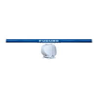
Details installation considerations for the antenna unit, including placement and mounting.

Monitor Unit Installation

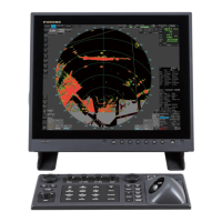
Provides installation procedure and location selection for the monitor unit.

Power Supply Unit Installation

Details installation considerations and mounting procedures for the power supply unit.

Processor Unit Installation

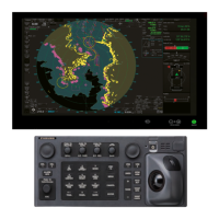
Outlines installation considerations and mounting for the processor unit.

Sensor Adapters (Option) Installation

Provides installation considerations for optional sensor adapters.

Intelligent HUB (Option) Installation

Details installation considerations for the optional Intelligent HUB.

Junction Box (Option) Installation

Provides requirements and installation details for junction boxes.

Wiring

Wiring Overview

Discusses cabling considerations and network construction for wiring.

Antenna Unit Wiring

Details cable fabrication and connection procedures for the antenna unit.

Processor Unit Wiring

Explains how to connect cables to terminals in the processor unit.

Monitor Unit Wiring

Covers wiring considerations and menu settings for the monitor unit.

LAN Signal Converter Kit (Option) Wiring

Explains the application and installation of the LAN Signal Converter Kit.

Settings and Adjustments

Accessing Radar Installation Menu

Guides on accessing the Radar Installation Menu for radar adjustments.

Aligning the Heading

Details the procedure for aligning the antenna unit's heading.

Adjusting Sweep Timing

Explains how to adjust sweep timing to prevent display symptoms.

Suppressing Main Bang

Provides steps to suppress main bang (clutter) on the radar display.

Dual Radar Display Configuration

Covers enabling and configuring the dual radar display.

Other Settings Overview

Describes menu items not previously covered, including Echo Adjustments.

Network Transmission Settings

Explains how to set up network transmission between ECDIS and radar.

Synchronization With Ship's Clock

Guides on activating synchronization with the ship's clock.

Input/Output Data

Processor Unit Data

Details input and output data for the processor unit.

IEC 61162 Sentences

Lists input and output sentences according to IEC 61162 standards.

Appendix 1 JIS Cable Guide

Appendix 2 Rod Terminals

Appendix 3 Digital Interface

Related product manuals