5
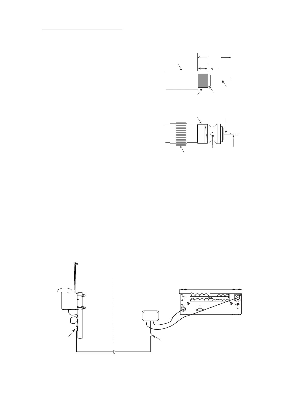
How to attach the plug M-P-7
Lay the coaxial cable and attach an M-type plug (if necessary) to the cable as
follows.
1. Remove the sheath by 30 mm.
2. Bare 23 mm of the center conductor. Trim
braided shield by 5 mm and tin.
3. Slide coupling ring onto cable.
4. Screw the plug assembly on the cable.
5. Solder plug assembly to braided shield
through solder holes. Solder contact sleeve
to conductor.
6. Screw coupling ring into plug assembly.
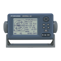
1.1.3 GPS/VHF combined antenna
Install the combined antenna unit referring to the outline drawing. When selecting a
mounting location for the antenna, keep in mind the following points.
• Select a location out of the radar beam. The radar beam will obstruct or prevent
reception of the GPS satellite signal.
• There should be no interfering object within the line-of-sight to the satellites. Objects
within line-of-sight to a satellite, for example, a mast, may block reception or prolong
acquisition time.
• Mount the antenna unit as high as possible. Mounting it this way keeps it free of
interfering objects and water spray, which can interrupt reception of GPS satellite
signal if the water freezes.
• Also, refer to the antenna installation guidelines page 3.
Outdoor
Indoor
N-P-8DFB
N-P-8DFB
Distributor DB-1
GPS
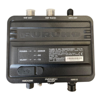
UAIS Transponder
VHF
RG-10U/Y
Installation overview of GPS/VHF combined antenna
Sheath
30 mm
5 mm
2 mm
Conductor
Insulator
Braided shield
Plug assembly
Contact sleeve
Cut conductor here.
Solder both
sides of hole.
Coupling ring
 Loading...