D
dana73Jul 31, 2025
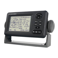
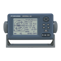
Why my Furuno UAIS TRANPONDER FA-150 Marine Radio cannot transmit or receive?
- VVincent WhiteJul 31, 2025
If your Furuno Marine Radio cannot transmit or receive, first ensure that the VHF antenna cable is securely fastened. Next, inspect the VHF antenna for any signs of damage. If you're trying to send a TX message, try using a different TX channel by navigating to MENU, then MSG, then CREATE MSG, then SET MSG TYPE, and finally CHANNEL.