This document provides a service manual for the Fusion Power Plant fp-9001d, a 1-channel high-efficiency 2-ohm stable D-CLASS amplifier. It includes an exploded view, a comprehensive parts list, and block diagrams for the PWM, PWM2, and INPUT/AUDIO sections, along with PCB board layouts.
Function Description
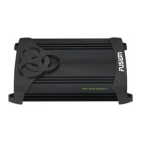
The Fusion Power Plant fp-9001d is a monoblock (1-channel) D-Class amplifier designed for high efficiency and stable operation at 2 ohms. Its primary function is to amplify audio signals, typically for driving subwoofers, given its single-channel design and emphasis on power output. The amplifier incorporates several protection features to ensure reliable operation and longevity.
The signal path begins with L-Input and R-Input, which pass through input buffers. These signals can be processed as "Flat" (from 5 to 500Hz), or routed through a "Low Pass Filter" (from 30 to 300Hz) and a "Sub Sonic" filter (from 20 to 55Hz). A "Bass Control" feature provides up to +18dB of boost at 46Hz, allowing users to tailor the low-frequency response. The amplifier also includes a "Remote Control" input for external control.
The processed signal then goes through a buffer and is fed to the FET Driver (HIP4080) and subsequently to the Final Stage, which consists of FETs or an LC Filter, delivering the amplified 1CH Output. The power supply section features a DC/DC Converter, Rectifier, and Filter, providing B+, B++, B--, and B- rails. Protection circuits include DC Offset Adjust, Output Adjust, DC Offset Protection, Overload Protection, and Thermal Protection, safeguarding the amplifier from various operational faults.
Important Technical Specifications
The parts list provides detailed component information, which can infer some technical specifications:
Capacitors:
- High-Efficiency Capacitors: The amplifier utilizes a wide range of capacitors, including ceramic chip capacitors (e.g., 100PF CH, 104 X7R, 220P X7R, 332 X7R, 334 X7R, 47P X7R), electrolytic capacitors (e.g., 0.1/50 4x7 SRA, 1/50 5x11 SHL, 2.2/50 5x11 SHL, 2.2/50 4x7 SRA, 10/16 5x11 SHL, 22/16 5x11 SHL, 22/16 5x7 SRA, 100/16 5x11 SHL, 100/16 6.3x7 SRA, 220/16 6.3x11 SHL, 470/16 8x11.5 SHL, 47/16 5x11 SHL, 47/25 5x11 SHL, 1000/35 12.5x20 SHL, 2200/25 16x25 SXE, 3300/63 25.4x30 SMH, 4700/80 35x30 DL), and Mylar film capacitors (e.g., 102 "j" MINI, 102 (0.001/50), 392 "J", 472 "J", 2A474K, 104/63V, 124/63V, 153/63V, 184/63V, 223/63V, 224/63V, 273/63V, 334/63V, 473/63V, 563/63V, 683/63V). These indicate a robust filtering and energy storage system for stable power delivery.
- Capacitor Values: Capacitors range from picofarads (pF) to microfarads (µF), with voltage ratings up to 80V, suggesting a design capable of handling significant power.
Resistors:
- Wide Range of Resistors: The parts list includes a comprehensive array of resistors, from 1/8W to 5W, with values spanning from 0 ohms (jumpers) to 1M ohm. This indicates precise control over current and voltage in various parts of the circuit.
- Specific Resistor Types: Includes chip resistors (2012 TYPE) and metal film resistors (M-TYPE), ensuring accuracy and stability.
Semiconductors:
- Diodes: Fast recovery diodes (FR104), general-purpose diodes (IN4002, IN4148M, IN5402), and Zener diodes (LL4148) are used for rectification, signal clamping, and voltage regulation.
- Transistors: Bipolar junction transistors (KTA1023Y, KTC1027Y, KTC3198Y, 2SB631E, KTC2800Y, MPSA06, MPSA56) and chip transistors (KTC4373Y) are used for switching and amplification.
- MOSFETs: IRFP064N and RFP70N06 MOSFETs are critical for the D-Class output stage, known for their high efficiency in switching applications. J112 FETs are also listed.
- Integrated Circuits (ICs):
- NJM13700D, CA3290E, HIP4080IP, CA5470E, NE5532AP, KA7812, KIA78L06, KA7912, NJM2904L SIP, CD4013BCM, CD4069UBCM, KIA494AF: These ICs indicate the presence of operational amplifiers (NE5532AP, NJM2904L), voltage regulators (KA7812, KIA78L06, KA7912), PWM controllers (KIA494AF), and logic gates (CD4013BCM, CD4069UBCM), which are essential for the amplifier's control, signal processing, and power management. The HIP4080IP is specifically identified as the FET Driver in the block diagram.
Inductors and Transformers:
- Toroids/Chokes: Various toroids and coil chokes (e.g., Ф 61, Ф 32, 1.5pie 32T, 1.5pie 18T) are used for filtering and energy storage in the power supply and output stages, crucial for D-Class amplifier efficiency.
Connectors and Switches:
- Pin Headers: 5-pin, 6-pin, and 9-pin headers (2.54mm pitch) are used for internal connections.
- RCA Jacks: JE0400600BG 4P GOLD B/B RCA jacks are used for audio inputs, suggesting high-quality signal transfer.
- Terminal Screws: 3P GOLD and 4P GOLD terminal screws are used for power and speaker connections.
- SW SL SK43D01G6 4C3P 6MM: A switch for control functions.
Protection Features:
- Fuses: ATC-40A fuses are included for overcurrent protection.
- Relay: CT11D12S relay for switching and protection.
- Thermistors: 150K thermistors for thermal protection.
- Variable Resistors (V/R SEMI): 3B20K, 3B50K, and 6MM 500B variable resistors for adjustments.
Usage Features
- 1-Channel Monoblock Design: Optimized for driving a single subwoofer or a set of subwoofers in parallel, providing dedicated bass amplification.
- High Efficiency (D-Class): D-Class amplifiers are known for their high power efficiency, meaning less heat generation and more power delivered to the speakers compared to traditional Class A/B designs. This also allows for a more compact design.
- 2 Ohm Stable: Capable of operating stably with speaker loads down to 2 ohms, offering flexibility in speaker configuration and maximizing power output.
- Adjustable Filters:
- Low Pass Filter: Adjustable from 30Hz to 300Hz, allowing users to precisely control the upper frequency limit of the amplified signal, essential for integrating a subwoofer with main speakers.
- Sub Sonic Filter: Adjustable from 20Hz to 55Hz, designed to filter out extremely low frequencies that are inaudible and can cause damage to subwoofers, improving sound quality and speaker protection.
- Bass Control: Provides up to +18dB of bass boost at 46Hz, enabling users to enhance the low-frequency impact according to their preferences and music genre.
- Remote Control Input: Allows for convenient remote adjustment of amplifier settings, typically bass level, from the driver's seat.
- Comprehensive Protection Circuits: Includes DC Offset Protection, Overload Protection, and Thermal Protection, ensuring the amplifier's safety and reliability under various operating conditions. This protects both the amplifier and connected speakers from damage due to faults or extreme conditions.
- Input Buffers: Help maintain signal integrity and prevent loading effects on the source unit.
Maintenance Features
The service manual provides detailed information crucial for maintenance and repair:
- Exploded View: Clearly illustrates the mechanical assembly of the amplifier, showing the location and relationship of all physical components. This is invaluable for disassembly and reassembly during repairs.
- Components: Includes chassis parts (BKTS 2184, 2202, 2203), main and sub PCBs (PP900.1MA, QX900.1PWM, QX900.1SUB), heatsinks (HSPP004-01), and various fasteners (screws, spacers).
- Parts List: A comprehensive list of all electronic components with their codes, names, standards, quantities, and remarks (e.g., capacitor values, resistor values, IC types, locations on the PCB). This allows technicians to identify and order exact replacement parts.
- Detailed Component Information: From basic resistors and capacitors to complex ICs and MOSFETs, every component is listed, facilitating troubleshooting and component-level repair.
- Block Diagrams: Provide a high-level overview of the amplifier's functional sections (PWM, PWM2, INPUT/AUDIO), illustrating signal flow and interconnections between different modules. This helps in understanding the amplifier's operation and isolating faulty sections.
- PWM1 Diagram: Details the pulse-width modulation control circuit, including ICs like KIA494AF and NJM2904, and various transistors and passive components responsible for generating the PWM signals for the output stage.
- PWM2 Diagram: Focuses on the power supply and output stage, showing the DC/DC converter, rectifier diodes (U30D20C), MOSFETs (IRFP064N, RFP70N06), and voltage regulators (7812P, 7912P, 78L06), along with fuses and thermal protection.
- INPUT/AUDIO Diagram: Illustrates the input signal processing, including input buffers (NE5532P), filters, bass control (CA5470), and the NJM13700D IC, which likely handles variable gain or other signal conditioning.
- PCB Board Layouts: Visual representations of the printed circuit boards (Main PCB, Sub PCB, PWM PCB) showing component placement and traces. These are essential for component identification on the physical board, tracing signals, and diagnosing issues.
- Multiple PCB Views: Includes different layers or views of the PCB (e.g., fp-9001d PCB BOARD, fp-9001d PCB BOARD-SUB, fp-9001d PCB BOARD-PWM), providing a complete picture for repair.
- Troubleshooting Support: The detailed diagrams and parts list enable technicians to systematically troubleshoot problems by checking voltages, signals, and component integrity at various points in the circuit. The protection features (overload, thermal, DC offset) also provide diagnostic indicators for specific fault conditions.
- Component Sourcing: The comprehensive parts list with codes and standards simplifies the process of sourcing replacement components, ensuring that repairs can be performed with original or equivalent parts.