Dual RCA cable (1 per zone, for stereo speakers) (Signal and Speaker Connection Considerations, page 3)
Single RCA cable and RCA splitter (1 per zone, for mono subwoofer or bridged output for speakers) (Signal and Speaker Connection Considerations, page 3)
Cable ties (optional)
Mounting Considerations
CAUTION
In high ambient temperatures and after extended use, the device enclosure may reach temperatures deemed dangerous to touch. Therefore the device must be installed in a location
where it will not be touched during operation.
NOTICE
This device should be mounted in a location that is not exposed to extreme temperatures or conditions. The temperature range for this device is listed in the product specifications.
Extended exposure to temperatures exceeding the specified temperature range, in storage or operating conditions, may cause device failure. Extreme-temperature-induced damage
and related consequences are not covered by the warranty.
This device is designed for installation only in a dry location. Installing this device in a location where it may come in contact with water or become submerged may result in damage.
Water damage is not covered by the warranty.
The device must be mounted in a location that does not interfere with the fuel tank or electrical wiring.
The device must be mounted in a location where it is not exposed to water.
The device must be mounted in a location with adequate ventilation where it is not exposed to extreme temperatures.
If the device is mounted in an enclosed space, you should install a cooling fan with appropriate ducts to aid in airflow.
The device should be mounted so that the cables can be connected easily.
To avoid interference with a magnetic compass, the device should be installed at least 55 cm (22 in.) away from a compass.
The device should not be mounted in close proximity to other navigation-critical equipment, antennas, or radiocommunication equipment on the
vessel.
Mounting the SG-DA61500/SG-24DA61500 Signature Series Device
NOTICE
If you are mounting the device in fiberglass, when drilling the pilot holes, it is recommended to use a countersink bit to drill a clearance counterbore through only the top gel-coat layer.
This will help to avoid cracking in the gel-coat layer when the screws are tightened.
NOTE: Screws are included with the device, but they may not be suitable for the mounting surface.
Before you mount the device, you must select a mounting location and determine what screws and other mounting hardware are needed for the surface.
1. Place the device in the mounting location and mark the location of the pilot holes.
2. Drill a pilot hole for one corner of the device.
3. Loosely fasten the device to the mounting surface with one corner and examine the other three pilot-hole marks.
4. Mark new pilot-hole locations if necessary, and remove the device from the mounting surface.
5. Drill the remaining pilot holes.
6. Secure the device to the mounting location.
Removing the Cover
You must remove the cover to reach the connectors and configuration controls on the amplifier.
1. Using the included 3 mm hex key, remove the screws that secure the cover to the amplifier.
2. Lift the cover off of the amplifier and set it aside until after you have finished making all of the connections and configured the amplifier.
Connection Considerations
NOTICE
The wiring (not included) from the battery to the amplifier must run through an inline fuse or circuit breaker (not included) as close to the battery as possible. You must connect the
positive wire to the fuse or circuit breaker. Connecting the amplifier to power without an inline fuse or circuit breaker may result in a fire if there is a short in the cable.
You must turn off the audio system before making any connections to the amplifier. Failure to turn off the audio system may result in damage to the audio system.
All terminals and connections must be protected from contact with the vessel chassis and with each other. Improper terminal or wire contact may result in damage to the audio system.
You must first connect the amplifier to the ground before making any other wiring connections (Connecting to Power, page 2) .
You must connect the positive wire to the battery only after you have completed all other wirings to the amplifier.
If your stereo does not have a remote turn-on signal wire, you must connect the amplifier to a switched power source.
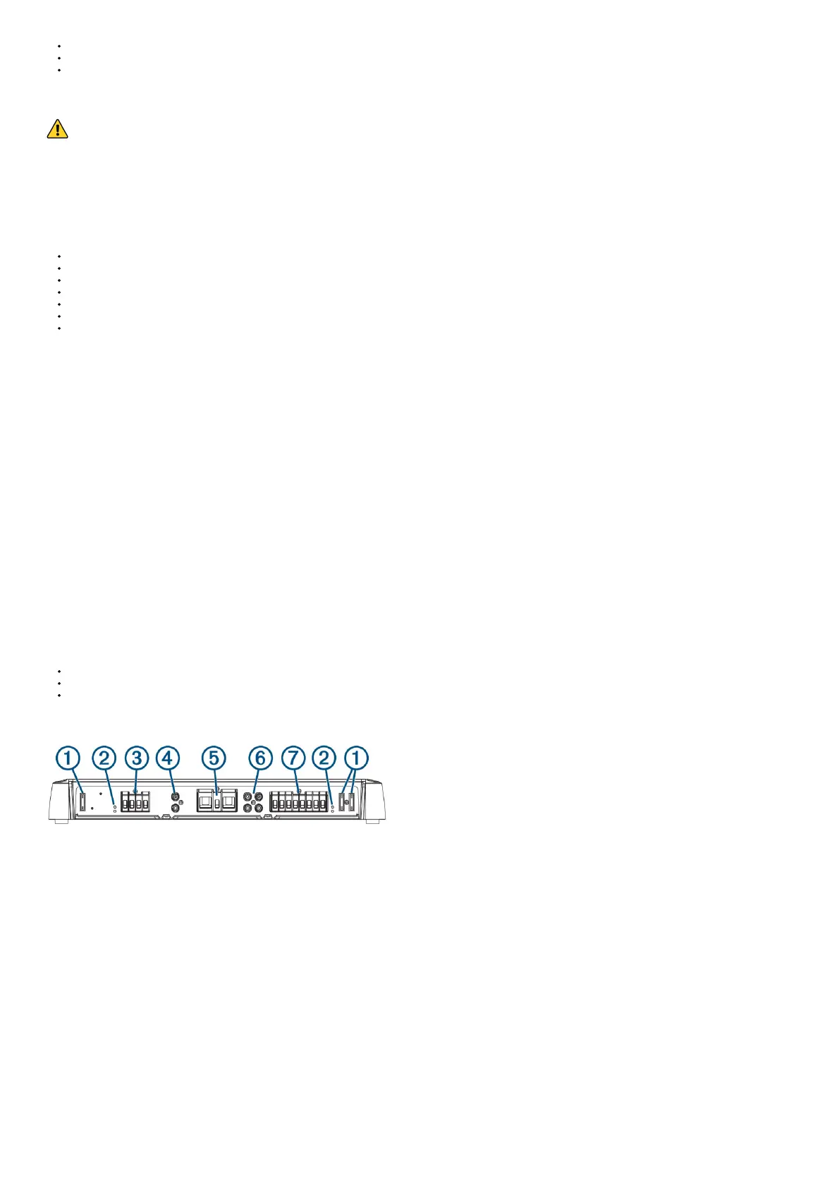
Port Identification
1 Fuses. See the product specifications for replacement details.
2 POWER and PROT (protection) LED indicators (Troubleshooting, page 5)
3 Zone 1 speaker terminals
4 Zone 1 RCA input
5 Power, ground, and amplifier turn-on terminals
6 Zones 2 and 3 RCA inputs
7 Zones 2 and 3 speaker terminals
Connecting to Power
You must connect the power wire to the battery through an inline fuse or a circuit breaker.
You must use the appropriate gauge of wire (not included) to connect the amplifier to power and ground, based on the total amperage and the length of the cable run (Power Cable
Gauge Guide, page 2).
1. Route the appropriate gauge of wire to the amplifier and to a ground location on the boat.
2. Using the included 3 mm hex key, connect the ground wire to the GND terminal on the amplifier.

 Loading...