Applicable systems: Futaba S-FHSS 2.4GHz system and TM-FH RF Module
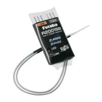
R2001SB
S-FHSS 2.4GHz System
S.BUS Port and 1 Channel (CH3) for Conventional System
Receiver
56%6SHFLÀFDWLRQV
S-FHSS 2.4GHz system/S.BUS port and 1 channel for conventional system receiver
• Dual antenna diversity
• Size: 0.83 x 1.65 x 0.21 in. (21.1 x 41.8 x 5.3 mm)
• Weight: 0.15 oz. (4.2g)
Thank you for purchasing a Futaba R2001SB S-FHSS 2.4GHz compatible receiver.
The R2001SB has an S.BUS system output port and a conventional system channel output. It can also be used with
conventional system servos, etc. in addition to S.BUS system compatible servos and gyros.
LED Indication
Green Red Status
Off Solid No signal reception
Solid Off Receiving signals
Blink Off Receiving signals but ID is unmatched
Alternate blink Unrecoverable error (Memory, etc.)
Antenna installation precaution
Do not cut or bundle the receiver antenna wire.
Do not bend the coaxial cable. It causes damage.
The antenna should not be pulled.
Keep the antenna as far away from the motor, ESC
and other noise sources as you possibly can.
Do not touch the antenna to metal, carbon, or other
conductive material.
Be sure that the two antennas are placed at 90
degrees to each other.
• The R2001SB has two antennas. In order to maximize signal
reception and promote safe modeling Futaba has adopted a diversity
antenna system. This allows the receiver to obtain RF signals on
both antennas and fly problem-free.
Antenna installation for carbon fuse
WARNING
The antenna portion of 30mm tip must be fully
exposed.
• Please make sure that the exposed portion won't slide back in the
fuse due to wind pressure or other force during the flight session.
Usage precaution
• Futaba S-FHSS system does not work with current Futaba FASST/
FASSTest/T-FHSS system. Futaba FASST/FASSTest/T-FHSS sys
-
tem and S-FHSS system are not compatible to each other.
WARNING
Wrap the receiver with something soft, such as foam
rubber, to avoid vibration. Moreover, the receiver must
not get wet.
Do not short-circuit the connectors.
Do not expose the receiver to high temperatures.
• The shrink cover could become distorted.
Do not break the tube.
• Could cause a short circuit.
When inserting and removing a connector, hold the
receiver tightly.
• Be careful so that a tube doesn't come off.
Please refer the table below for LED status vs
receiver's condition.
1M23N32102
R2001SB
Linkswitch
Antenna
S.BUSPort
CH3outputconventionalsystem
/Batteryterminal
LED
S.BUSequipment
• Power requirement: 4.8V to 7.4V
• Battery F/S Voltage: 3.8V
* Be sure that when using ESC's regulated output the current capacity
of the ESC meets your usage condition.
* The Battery F/S voltage is set for 4-cell NiCd/NiMH battery. Bat-
tery F/S function doesn't work properly when a different type
of battery is used.
* The fail safe function can be set for each channel. However, it dif-
fers according to the transmitter. When you use TM-FH RF Module,
the fail safe function can be set for channel 3 only.
* S.BUS port: R2001SB can be used with up to 8 channels. However,
it differs according to the transmitter. An unused channel is a neutral
signal. The F/S setting channel at F/S is F/S position
.
Another, it is
Hold signal.
Directionoftheconnectors
90˚
Antennainstallation
The power supply from S.BUS port is
also possible.