Do you have a question about the FUTABA R7208SB and is the answer not in the manual?
Procedure to enable FASSTest12CH Telemetry OFF mode for receiver.
Steps to link two receivers on an aircraft for dual receiver capability.
Explanation of telemetry system usage with dual receivers.
Guidance on servo compatibility, antenna placement, and avoiding interference.
Precautions during linking and connector usage to prevent damage or hazards.
FCC, IC, and EU compliance information for the R7208SB receiver.
Detailed specifications including system, size, weight, and power requirements.
Explanation of LED indicators for various receiver states and modes.
Step-by-step guide for linking the receiver to the transmitter.
Procedure to change receiver channel allocations and mode selection.
Steps to activate the Dual RX Link mode for enhanced safety.
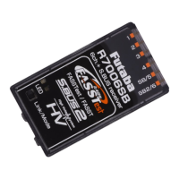
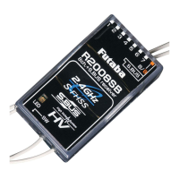
This document describes the Futaba R7208SB receiver, a device designed for use with FASSTest-capable transmitters in radio-controlled systems. It supports bidirectional communication and can integrate multiple optional telemetry sensors.
The R7208SB receiver operates on the FASSTest bidirectional communication system, allowing it to send telemetry data back to a compatible transmitter. It features 8 standard PWM outputs and also supports S.BUS and S.BUS2 for expanded connectivity. The S.BUS2 port is particularly versatile, enabling the connection of various telemetry sensors that can provide real-time data to the transmitter.
A key feature of the R7208SB is its ability to operate in a Dual RX Link System. This setup involves using two receivers in a single aircraft. If one receiver experiences a communication failure, the other receiver can take over, enhancing reliability and safety. In this mode, the SB2/RX port is dedicated to reception, and specific CH modes (B, C, D, F, G) are used for S.BUS output and S.BUS2 input/output.
The receiver includes an LED indicator that provides visual feedback on its status. Different LED patterns (solid, blinking, alternating) indicate various operational states such as no signal reception, receiving signals, waiting for link, unrecoverable errors, and specific conditions within the Dual RX Link Mode (e.g., external receiver error, S.BUS signal reception).
The R7208SB also offers configurable channel modes, allowing users to adjust channel allocations. This is particularly useful when operating in a dual receiver setup, as it enables precise control over which channels are managed by each receiver.
To establish a link between the R7208SB and a FASSTest transmitter, both devices should be brought within 20 inches (half meter) of each other. The transmitter must be powered on and placed into its receiver linking mode, followed by powering on the receiver. The receiver will wait for 2 seconds for the linking process to begin before returning to normal operation mode. A successful link is indicated when the receiver's LED changes from blinking red to solid green. It's crucial to confirm that the receiver is under the control of the correct transmitter, especially in environments with multiple FASSTest systems operating simultaneously, to prevent accidental linking to the wrong transmitter. If the transmitter's system type is changed, the receiver will need to be re-linked.
To change the channel mode, the receiver must be powered on with the transmitter off. The user then presses and holds the SW button for 5 to 10 seconds. When the LED blinks red to orange, the SW can be released. The LED will then blink red twice, indicating the current mode. Each subsequent press of the SW advances the receiver to the next mode. Once the desired mode is reached, pressing and holding the SW for more than 2 seconds will confirm the change, indicated by the LED blinking green with red. After changing the mode, the receiver's power must be cycled off and back on.
To configure the Dual RX Link Mode, the receiver must be powered on with the transmitter off. The user presses and holds the SW button for 5 seconds or more. The LED will blink orange, then green, and then orange slowly. Releasing the SW at the orange slow blink will set the mode. The LED will blink green once to confirm. To return to the off mode, the SW is pressed again, and the LED will flash green once. To activate the Dual RX Link Mode, the SW is pressed again, and the LED will blink green twice. After setting the desired mode, the receiver power should be turned off and restarted.
In this mode, the receiver's LED will blink orange. To activate or deactivate this mode, the receiver is powered on with the transmitter off. The SW is pressed and held for 5 seconds or more. The LED will blink orange, then green, then orange slowly. Releasing the SW at the orange slow blink will set the mode. The LED will blink green once to confirm. To return to the off mode, the SW is pressed again, and the LED will flash green once. To activate the FASSTest12CH Telemetry OFF Mode, the SW is pressed again, and the LED will blink green twice. After setting the desired mode, the receiver power should be turned off and restarted.
Proper antenna installation is crucial for optimal performance. The antenna should be secured to prevent movement inside the aircraft. The coaxial cable part should be gently bent, and the antenna itself should not be bent. A 90-degree angle for the antenna is often recommended for best signal reception.
After any configuration changes or power cycles, it's important to check the receiver's status. This is done by powering on the receiver with the transmitter off. The receiver will enter a link waiting state, and the LED will flash to indicate the current CH output mode. In Dual RX Link Mode, the MODE LED will indicate if an external receiver is experiencing an error, if the S.BUS signal is not received, or if the S.BUS signal is being received from an external receiver.
It is important to ensure that the receiver is not exposed to excessive vibration, moisture, or extreme temperatures. The R7208SB is designed for use in model aircraft and should be handled with care. Any modifications not approved by the manufacturer could void the user's authority to operate the equipment. The receiver should be protected from fuel or water exposure. It should also be kept away from conductive materials to avoid short circuits.
Regularly inspect the antenna for any damage or wear. A damaged antenna can lead to a decrease in range and reliability. Ensure the antenna is mounted securely and that its wires are not pinched or frayed. The antennas must be positioned in a way that minimizes interference from other electrical noise sources, such as motors or ESCs. For optimal signal reception, the two antennas should be placed at 90 degrees to each other.
If the receiver experiences issues, checking the LED status is the first step in troubleshooting. Different LED patterns indicate specific problems, as detailed in the LED Indication table. If an unrecoverable error occurs (e.g., EEPROM error), the LED will alternate between red and green. In such cases, further investigation or professional servicing may be required. If the receiver fails to link, ensure the transmitter is in linking mode and that there are no other FASSTest systems causing interference. If the problem persists, cycling the power and restarting the linking process is recommended.
| Frequency | 2.4 GHz |
|---|---|
| Telemetry | Yes |
| S.BUS | Yes |
| S.BUS2 | Yes |
| Modulation | FASSTest |
| Compatibility | FASSTest |
| Channels | 8 |