Do you have a question about the FUTABA R7003SB and is the answer not in the manual?
Covers safe handling, vibration protection, and avoiding short circuits.
Proper antenna mounting for optimal signal reception and strain relief.
Explains LED indications for signal reception and errors.
Details default channel output configurations for the receiver.
Identifies compatible Futaba FASSTest-2.4GHz transmitters.
Lists key technical details like size, weight, and power requirements.
Describes the simplified process for linking receiver to transmitter.
Important warnings to avoid injury during the linking process.
Details the available channel output modes and their LED indications.
Procedure to enable external voltage measurement mode.
Warnings and precautions for using the EXT-VOL mode and cable.
Corresponds gyro functions to specific receiver ports and channels.
Example connection of GYA431 gyro for airplane aileron control.
Steps to display battery voltage via transmitter using an adapter.
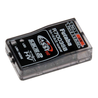
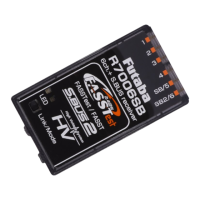
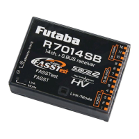
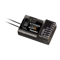
The Futaba R7003SB is a FASSTest-2.4GHz bidirectional communication system receiver, designed to work with FASSTest-compatible transmitters. It supports both S.BUS2/S.BUS ports and conventional system receiver functionalities. This receiver allows for bidirectional communication with a FASSTest Futaba transmitter via the S.BUS2 port, enabling the use of an impressive array of telemetry sensors. The R7003SB can acquire flight information from the model by connecting optional telemetry sensors. It also features standard PWM output ports and S.BUS output ports. The 4 ports of the R7003SB can be configured to output channels from 11 different modes.
When using the R7003SB, it's important to note that analog servos cannot be used in the FASSTest 12CH mode. The receiver is exclusively compatible with FASSTest-capable transmitters. For safety, changes or modifications not expressly approved by the responsible party could void the user's authority to operate the equipment. The R7003SB receiver should be protected from vibration using materials like foam rubber or Velcro, and it must be shielded from moisture. Additionally, it's crucial to keep the receiver away from conductive materials to prevent short circuits.
A critical usage precaution involves the S.BUS2 port: do not connect servos or gyros that are not S.BUS2 compatible to this port, as this could lead to malfunctions. When powering up the system, always turn on the transmitter first, followed by the receiver, and then verify the operation of all servos before flight. Avoid inserting or removing servo connectors while the receiver power is ON. Since S.BUS servos automatically switch their operation mode based on the signal type (S.BUS or PWM) from the receiver, connecting or removing a connector while power is ON can cause an S.BUS servo to be erroneously recognized and potentially stop functioning.
For antenna installation, it is crucial not to cut or bundle the receiver antenna wire, and the coaxial cable should not be bent, as this can cause damage. The antennas must be mounted in a way that ensures they are strain-relieved. To minimize interference, keep the antenna as far away as possible from the motor, ESC, and other noise sources. The R7003SB features two antennas, and for optimal signal reception and safe modeling, they should be placed at a 90-degree angle to each other. This diversity antenna system allows the receiver to obtain RF signals from both antennas, ensuring problem-free flight. For carbon fuselages, a critical safety measure is to leave 30mm at the tip of the antenna fully exposed and secure it to prevent movement or re-entry into the aircraft.
The R7003SB can operate with only 3 channels if it does not utilize the S.BUS/S.BUS2 system. However, if the S.BUS/S.BUS2 system is employed, the receiver can utilize the maximum channel capacity of the transmitter. To leverage the S.BUS/S.BUS2 system, S.BUS/S.BUS2 servos must be used.
The receiver's LED provides important status indications. A solid red LED indicates no signal reception, while a solid green LED signifies that signals are being received. An alternating blink (green and red) indicates an unrecoverable error, such as an EEPROM issue.
Linking the receiver to the transmitter is made easy with the Easy Link ID feature, which allows FASSTest receivers to link to compatible transmitters without needing to press a link button on the receiver. To link, bring the transmitter and receiver within 20 inches (half meter) of each other. Turn on the transmitter and place it into the receiver linking mode. Then, turn on the receiver. Linking is complete when the receiver's LED changes from blinking red to solid green. It is important to consult the transmitter's operation manual for detailed instructions on placing it into linking mode. In environments with multiple FASSTest systems, there's a rare possibility of the receiver linking to the wrong transmitter. Always double-check that your receiver is under the control of your transmitter. If the transmitter's System Type is changed, the receiver will need to be re-linked. Linking is also required when a new model is created from a model selection.
A critical warning during the linking procedure: do not perform linking while the motor's main wire is connected or the engine is operating, as this may result in serious injury. After linking is complete, cycle the receiver power and ensure proper linkage. Always power up the system in the order of transmitter first, then receiver. If the R7003SB was previously linked to another transmitter, ensure that the previous transmitter is not operating while linking the receiver to the new transmitter.
The R7003SB supports various channel allocations, offering 11 modes. To change the channel mode, press and hold the Link/Mode button on the R7003SB receiver while the transmitter is OFF. Turn on the receiver while holding the button, then release it. The LED will blink red with green. Each press of the Mode/Link button advances the receiver to the next mode. Once the desired mode is reached, press and hold the Mode/Link button for more than 2 seconds. When the LED blinks green with red, the mode change is complete. Finally, cycle the receiver power off and back on again after changing the channel mode. The LED will show the CH Mode 5 seconds after the receiver is turned ON.
The R7003SB also has an "EXT-VOL Mode" for external voltage measurement. To activate this, turn on the receiver (transmitter OFF), and the LED will light up red. Press and hold the Mode/Link button for 5 to 10 seconds. If held longer than 10 seconds, it indicates a mistake, requiring a power cycle and re-attempt. The LED will then blink green rapidly. Release the Mode/Link button. Each press of the Mode/Link button advances the receiver to the next mode. When the desired mode is reached, press and hold the Mode/Link button for more than 2 seconds. When the LED blinks green with red, the mode change is complete. Cycle the receiver power off and back on again after changing the EXT-VOL Mode. In EXT-VOL Mode, the LED blinks green twice, while in Servo Mode (Default), it blinks green once.
When using the EXT-VOL CABLE (optional), it connects to Port 2 of the R7003SB. A warning: do not touch the wiring, as there is a risk of electric shock. Do not connect to Extra Voltage before turning on the receiver. When not using EXT-VOL, "EXT-VOL Mode" must be turned OFF. Do not connect any EXT-VOL CABLE other than port 2 of the R7003SB.
When using the R7003SB Receiver with the GYA430 or GYA431 gyros, the provided table shows the corresponding gyro functions and effective port usage. The servo controlled by a gyro should be connected to that gyro. Refer to each gyro manual for specific details.
The R7003SB can display the voltage of a receiver battery on a transmitter. To display the voltage of another battery (e.g., a drive battery), an optional CA-RVIN-700 adapter is required. First, purchase the adapter. Then, change the R7003SB into "EXT-VOL Mode" as described above. Note that if "EXT-VOL Mode" is used, port 2 cannot be used as a servo channel. Following the CA-RVIN-700 manual, branch the battery wiring and connect it. Finally, connect one side of the EXT-VOL CABLE to port 2 of the R7003SB.
| Channels | 3 |
|---|---|
| Telemetry Support | Yes |
| Weight | 10 g |
| Compatibility | FASSTest |
| Connector Type | Futaba |
| Voltage Range | 3.5V-8.4V |