Applicable systems: Futaba S-FHSS/FHSS-2.4GHz system and TM-FH RF Module
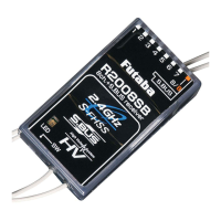
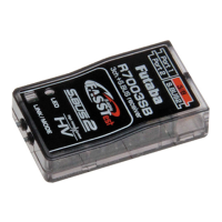
R2008SB
S-FHSS/FHSS-2.4GHz System
S.BUS Port and 8 Channels for Conventional System
Receiver
R2S% SpeciÀcations
S-FHSS/FHSS-2.4GHz system/S.BUS port and 8 channels for conventional system receiver
• Dual antenna diversity
• Size: 0.98 x 1.69 x 0.55 in. (24.9 x 42.8 x 14.0 mm)
• Weight: 0.34 oz. (9.5g)
• Power requirement: 4.8V to 7.4V
• Battery F/S Voltage: 3.8V
* Be sure that when using ESC's regulated output the current capacity of the ESC must meet your usage condition.
* The Battery F/S voltage is set for 4-cell NiCd/NiMH battery. Battery F/S function doesn't work properly when other type battery is used.
* The fail safe function can be set for each channel , however it differs according to the transmitter. When you use TM-FH RF Module , the fail safe function can be set
for 3-channel only.
* S.BUS port: R2008SB can be used up to 8 channels, however, it differs according to the transmitter. An unused channel is a neutral signal. The F/S setting channel at
F/S is F/S position
.
Another, it is Hold signal.
Thank you for purchasing a Futaba R2008SB S-FHSS/FHSS-2.4GHz compatible receiver.
The R2008SB has an S.BUS system output port and a conventional system channel outputs. It can also be used with
conventional system servos, etc. in addition to S.BUS system compatible servos and gyros, etc.
signal reception and promote safe modeling Futaba has
adopted a diversity antenna system. This allows the
receiver to obtain RF signals on both antennas and fly
problem-free.
Antenna installation for carbon fuse
WARNING
The antenna portion of 30mm tip must be fully
exposed.
• Please make sure that the exposed portion won't be slided
back in the fuse by the wind pressure or other force during
the flight session.
S.BUS connector insertion precau-
tion
DANGER
Do not insert a
connector, as shown
right.
• It will occur short-circuit, by
inserting this way. A short
circuit across the battery
terminals may cause
abnormal heat, fire and
burning.
Usage precaution
• Futaba S-FHSS/FHSS system does not work with cur-
rent Futaba FASST system. Futaba FASST system and
S-FHSS/FHSS system are not compatible each other.
WARNING
Wrap the receiver with something soft, such as
foam rubber, to avoid vibration. Moreover, The receiver
must not get wet.
Keep away from conductive material to avoid the
short circuit.
Antenna installation precaution
Do not cut or bundle the receiver antenna wire.
Do not bend the coaxial cable . It causes damage.
The antenna should not be pulled.
Keep the antenna away from the motor, ESC and
other noise sources as you can.
Be sure that the two antennas are placed at 90
degrees to each other.
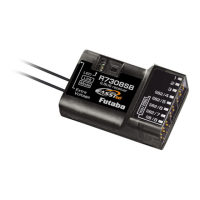
• The R2008SB has two antennas. In order to maximize
(Antenna installation)
90˚
Link switch
Antenna
LED
R2008SB
for conventional
system
Channel
1
Channel
7
Channel 8
output
for conventional
system
/Battery terminal
output
output
S.BUS
Port
(Connectors)
1M23N17474
Do not insert either a switch
or battery in this manner.
5HFHLYHU
DANGER
S.BUSS.BUS
CH8/Battery(8/B)
CH8/Battery(8/B)
CH7
CH7