EasyManua.ls Logo

FUTABA R6308SBT - User Manual

FUTABA R6308SBT
2 pages
Print Icon
To Next Page IconTo Next Page
Loading...
Applicable systems: Futaba FASST-2.4GHz (7ch/8ch/10ch/Multi-ch) system transmitter
R6308SBT
FASST-2.4GHz (7ch/8ch/10ch/Multi-ch) System with Telemetry
S.BUS2 / S.BUS Port and 8 Channels for Conventional System
Receiver
Compliance Information Statement
(for U.S.A.)
This device, trade name Futaba Corporation of America, model number
R6308SBT, complies with part15 of the FCC Rules. Operation is subject to the
following two conditions:
(1) This device may not cause harmful interference, and
(2) This device must accept any interference received, including interference
that may cause undesired operation.
(3) This module meets the requirements for a mobile device that may be used
at separation distances of more than 20cm from human body.
To meet the RF exposure requirements of the FCC this device shall not be co-
located with another transmitting device.
The responsible party of this device compliance is:
Futaba Service Center
3002 N Apollo Drive Suite 1, Champaign, IL 61822 U.S.A.
TEL (217)398-8970 or E-mail: support@futaba-rc.com (Support)
R6308SBT Specications
FASST-2.4GHz system(7CH/8CH/10CH/Multi-ch mode)/S.BUS2 and
S.BUS port and 8 channels for conventional system receiver
• Dual antenna diversity
• Size: 0.98 x 1.86 x 0.56 in. (24.9 x 47.3 x 14.3 mm)
• Weight: 0.38 oz. (10.9g)
• Power requirement: 3.7V to 7.4V(Voltage range: 3.5 to 8.4V)
Battery F/S Voltage: 3.8V
*The Battery F/S voltage is set for 4-cell NiCd/NiMH
battery. Battery F/S function doesn't work properly when other type battery is used.
• Extra Voltage port: 0
70V DC
* Be sure that when using ESCs regulated output the capacity of the ESC must
meet your usage condition.
Thank you for purchasing a Futaba R6308SBT FASST-2.4GHz compatible receiver.
The R6308SBT receiver features bi-directional communication
with a telemetry receiver unit (option) using the S.Bus2 port. Using the S.Bus2 port an impressive array of telemetry sensors may be utilized. It also
includes both standard PWM output ports and S.Bus output ports. This receiver distinguishes automatically FASST-2.4-GHz system 7ch or Multi-
ch/10ch / 8ch mode at the time of link operation with a transmitter. And high speed mode can be chosen.
LED Indication
Green Red Status
Off Solid No signal reception
Solid Off Receiving signals
blink Off ID of a signal is disagreement
Alternate blink Unrecoverable error (EEPROM, etc.)
(Antenna installation)
90˚
Please refer the table below for LED status vs
receiver's condition.
1M23N17459
S.BUS2
port
S.BUS port
(8/SB)
(S.BUS2)
R6308SBT
S.BUS Servo
S.BUS Gyro
HUB
HUB
HUB
HUB
Extra Voltage
Port
Link/Mode switch
Antenna
LED
Servo for conventional
system
Channel1 output
Channel8 output
Temperature
Sensor
RPM
Sensor
Voltage
Sensor
Voltage
Sensor
Altitude
Sensor
Altitude
Sensor
S.BUS2 Tool
Battery to 7/B
Itconnectswiththe
batteryforpower,etc.
Externalvoltageinput
cableofanoptionis
used.Thevoltageof
thebatterycanbe
displayedwitha
transmitter.
with telemetry
When using S.BUS, it is
necessary to change CH
mode into B or D.
HUB
Usage precaution
󾾝
WARNING
󾾛
Changes or modification not expressly approved by the
party responsible for compliance could void the user’s
authority to operate the equipment.
󾾙
The R6308SBT receiver should be protected from vibra-
tion by foam rubber, Velcro or similar mounting meth-
ods. Protect from moisture.
󾾛
Keep away from conductive materials to avoid short cir-
cuits.
󾾛
Don't connect to Extra Voltage before turning on a receiv-
er.
Antenna installation precaution
󾾛
Do not cut or bundle the receiver antenna wire.
󾾛
Do not bend the coaxial cable. It causes damage.
󾾛
The antennas must be mounted in such a way to assure
they are strain relieved.
󾾙
Keep the antenna as far away from the motor, ESC and
other noise sources as you possibly can.
󾾙
Be sure that the two antennas are placed at 90 degrees to
each other.
TheR6308SBThastwoantennas.Inordertomaximizesignal
reception and promote safe modeling Futaba has adopted a diversity
antenna system. This allows the receiver to obtain RF signals on both
antennas and fly problem-free.
Antenna installation for carbon fuselage
󾾝
WARNING
󾾙
You must leave 30mm at the tip of the antenna fully ex-
posed. The exposed antenna should be secured so that it
cannot move around or back inside of your aircraft.
(Typical installation)
Question and Answer IconNeed help?

Do you have a question about the FUTABA R6308SBT and is the answer not in the manual?

Summary

Usage Precautions and Warnings

General Warnings

Changes or modification not approved by the compliance party can void user authority. Protect from vibration and moisture.

Antenna Installation Precautions

Do not cut or bundle antenna wire. Do not bend coaxial cable. Mount antennas to ensure strain relief.

Antenna Placement and Orientation

Keep antennas away from noise sources and place them at 90 degrees to each other for diversity.

Antenna Installation for Carbon Fuselage

Carbon Fuselage Antenna Warning

Leave 30mm of antenna tip exposed and secure it to prevent movement within the aircraft.

Compliance Information

FCC Compliance Statement (USA)

Device complies with FCC Part 15. Operation subject to two conditions regarding interference and user authority.

Receiver Specifications

General Specifications

FASST-2.4GHz system, dual antenna diversity, size 0.98x1.86x0.56 in, weight 0.38 oz.

Power and Voltage Requirements

Power requirement 3.7V to 7.4V. Battery F/S voltage 3.8V for NiCd/NiMH. Extra Voltage port 0-70V DC.

S.BUS2 and S.BUS Functionality

S.BUS2 Communication

Extends S.BUS, supports bidirectional communication. Connect sensors to S.BUS2 port for telemetry.

S.BUS Compatibility

Standard S.Bus servos/gyros not for S.BUS2 port. S.BUS output supports conventional servos.

Linking and Mode Selection

Linking to Transmitter

Procedure to link receiver to transmitter via Link/Mode switch, including F/S position adjustment.

High Speed Mode; Telemetry Control

Toggle between Normal and High Speed modes. High speed mode disables sensors, only shows battery voltage.

Channel Mode Selection

Guide to changing channel allocations using the Link/Mode button and observing LED status.

Telemetry Receiver Unit Linking

Process to put R6308SBT into ID transmitting mode to link with telemetry receiver unit.

Overview

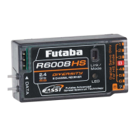
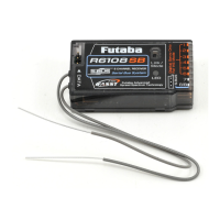
The Futaba R6308SBT is a FASST-2.4GHz compatible receiver designed for use with Futaba FASST-2.4GHz (7ch/8ch/10ch/Multi-ch) system transmitters. This receiver incorporates S.BUS2/S.BUS port functionality and provides 8 channels for conventional system receivers, making it suitable for a wide range of RC applications. A key feature of the R6308SBT is its bi-directional communication capability with an optional telemetry receiver unit via the S.BUS2 port. This allows for the integration of various telemetry sensors, providing real-time data feedback to the user. The receiver automatically distinguishes between FASST-2.4GHz 7ch, Multi-ch/10ch, or 8ch modes during the linking process with a transmitter and supports a high-speed mode for enhanced response.

Function Description:

The R6308SBT serves as the central receiving unit for control signals from a Futaba FASST-2.4GHz transmitter. It translates these signals into commands for servos and other components in an RC model. The S.BUS2 port is a significant enhancement, enabling a serial data bus system that simplifies wiring and allows for the connection of multiple S.BUS2-compatible devices, including telemetry sensors. These sensors can transmit data such as battery voltage, temperature, RPM, and altitude back to the transmitter (when an optional telemetry receiver unit is used), providing critical information for monitoring the model's status during operation. The receiver also features standard PWM output ports for conventional servos, offering flexibility in setup.

The dual antenna diversity system is a crucial design element for maximizing signal reception and promoting safe modeling. With two antennas, the receiver can obtain RF signals from both, reducing the risk of signal loss due, for example, to antenna orientation or shielding by the model's structure. The receiver's ability to operate in both normal and high-speed modes allows users to choose between telemetry functionality (normal mode) or faster response times (high-speed mode, which only transmits receiver battery voltage telemetry).

The R6308SBT supports various channel modes (Mode A, B, C, D) to accommodate different transmitter configurations and channel allocations. This flexibility ensures compatibility with a broad spectrum of Futaba FASST transmitters and allows users to customize the channel assignments to suit their specific model requirements. The linking process is straightforward, involving pressing and holding the Link/Mode switch on the receiver while powering it on, then linking with the transmitter. The LED indicator provides visual feedback on the receiver's status, including signal reception, ID disagreement, and error conditions.

Important Technical Specifications:

  • System Compatibility: FASST-2.4GHz system (7CH/8CH/10CH/Multi-ch mode)
  • Output: S.BUS2 and S.BUS port, 8 channels for conventional system receiver
  • Antenna System: Dual antenna diversity
  • Dimensions: 24.9 x 47.3 x 14.3 mm (0.98 x 1.86 x 0.56 in.)
  • Weight: 10.9g (0.38 oz.)
  • Power Requirement: 3.7V to 7.4V (Voltage range: 3.5 to 8.4V)
  • Battery F/S Voltage: 3.8V (set for 4-cell NiCd/NiMH battery; Battery F/S function may not work properly with other battery types).
  • Extra Voltage Port: 0 ~ 70V DC
  • Operating Temperature: Not explicitly stated, but generally designed for typical RC operating environments.

Usage Features:

  • Automatic Mode Detection: Automatically detects FASST-2.4GHz 7ch, Multi-ch/10ch, or 8ch modes during linking.
  • High-Speed Mode: Provides faster response times, though telemetry is limited to receiver battery voltage in this mode.
  • Telemetry Integration: Supports a wide array of telemetry sensors via the S.BUS2 port for real-time data feedback (requires optional telemetry receiver unit).
  • Channel Mode Flexibility: User-selectable channel modes (A, B, C, D) to match transmitter configurations and specific model needs.
  • S.BUS2 Connectivity: Simplifies wiring and expands connectivity for S.BUS2-compatible devices and sensors.
  • Dual Antenna Diversity: Enhances signal reception reliability by utilizing two antennas.
  • LED Status Indicator: Provides clear visual cues for receiver status, including signal reception, linking status, and error conditions.
  • Failsafe Functionality: Includes Battery F/S (Failsafe) at 3.8V for 4-cell NiCd/NiMH batteries, ensuring a controlled response in case of low battery voltage.
  • Extra Voltage Port: Allows for external voltage input, with the voltage displayable on the transmitter.

Maintenance Features:

  • Protection from Vibration: The receiver should be protected from vibration using foam rubber, Velcro, or similar mounting methods to ensure longevity and reliable operation.
  • Moisture Protection: It is crucial to protect the receiver from moisture to prevent damage to internal electronics.
  • Avoid Conductive Materials: Keep the receiver away from conductive materials to prevent short circuits.
  • Antenna Installation:
    • Antennas must be mounted to assure strain relief.
    • Keep antennas as far as possible from the motor, ESC, and other noise sources.
    • Ensure the two antennas are placed at a 90-degree angle to each other for optimal diversity performance.
    • For carbon fuselages, at least 30mm of the antenna tip must be fully exposed and secured to prevent movement.
    • Do not bend the coaxial cable, as this can cause damage.
    • Do not cut or bundle the receiver antenna wire.
  • Power-Up Sequence: Always power on the transmitter first, followed by the receiver, and ensure the receiver is properly linked before operation.
  • Regular Checks: After linking, cycle the receiver power and verify proper linkage. Before flight, always check the operation of all servos.
  • S.BUS Servo Configuration: When using S.BUS servos, their channels should be set using an SBC-1 channel changer, CIU-2 USB serial interface, or the programming software in the 18MZ transmitter.
  • No Hot-Plugging: Do not insert or remove servo connectors while the receiver power is ON.
  • ESC Compatibility: When using ESCs with regulated output, ensure the ESC's capacity meets the usage conditions.

FUTABA R6308SBT Specifications

General IconGeneral
BrandFUTABA
ModelR6308SBT
CategoryReceiver
LanguageEnglish

Related product manuals