Do you have a question about the FUTABA R7006SB and is the answer not in the manual?
Lists Futaba FASSTest-2.4GHz and FASST (Multi-ch,7ch) -2.4GHz transmitter systems compatible with the receiver.
Covers important safety and installation advice, including servo compatibility, mounting, and antenna handling.
Specific instructions for mounting antennas on carbon fiber aircraft to ensure proper signal reception.
Warnings and advice regarding the receiver linking procedure and connecting S.BUS servos/gyros.
Details the meaning of LED status lights for signal reception and linking states.
Provides key technical details including system compatibility, size, weight, and power requirements.
Explains how to change the receiver's channel allocations for different operational needs.
Describes the method to switch the receiver between FASSTest and FASST operating systems.
Step-by-step guide for establishing a communication link between the receiver and a FASSTest transmitter.
Details the S.BUS2 port's capability for bidirectional communication and telemetry sensor connection.
Instructions for linking the R7006SB receiver with the TMA-1 Telemetry Adapter.
Procedure to link the receiver to a FASST transmitter, including F/S position setting.
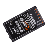
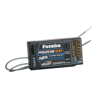
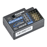
The Futaba R7006SB is a sophisticated 2.4GHz receiver designed for use with Futaba FASSTest and FASST system transmitters. This receiver offers bi-directional communication, enabling the use of an impressive array of telemetry sensors through its S.BUS2 port. In addition to the S.BUS2 and S.BUS output ports, it provides six standard PWM output ports for conventional system servos. The R7006SB can also be switched between FASSTest-2.4GHz and FASST (Multi-ch/7-ch) 2.4GHz systems, offering flexibility for various setups.
The R7006SB operates as a core component in a radio control system, receiving commands from a compatible Futaba transmitter and relaying them to servos and other connected devices. Its primary function is to provide reliable and secure control over a model.
In FASSTest mode, the receiver supports bidirectional communication, allowing telemetry data from connected sensors (via the S.BUS2 port) to be sent back to the transmitter for display. This real-time feedback on parameters like battery voltage, temperature, or altitude significantly enhances situational awareness during flight. The FASSTest system supports both 18-channel and 12-channel modes, offering extensive control capabilities.
When operating in FASST (Multi-ch/7ch) mode, the receiver functions as a standard control receiver, providing reliable signal reception for up to seven channels or multiple channels depending on the specific FASST mode selected. It's important to note that telemetry functions are not available in FASST mode.
The S.BUS2 and S.BUS ports are key features, allowing for simplified wiring and expanded connectivity. S.BUS2 supports bidirectional communication with telemetry sensors, while S.BUS provides a single-line connection for multiple S.BUS compatible servos or gyros, reducing cable clutter and simplifying installation. The six conventional PWM output ports allow for direct connection of standard servos, offering compatibility with a wide range of existing equipment.
The receiver incorporates a dual antenna diversity system to maximize signal reception and ensure safe modeling. This system continuously evaluates the signal strength from both antennas and automatically switches to the one with the best reception, enhancing reliability and minimizing the risk of signal loss, especially in challenging RF environments.
System Compatibility and Modes: The R7006SB is compatible with Futaba FASSTest-2.4GHz and FASST (Multi-ch,7ch)-2.4GHz system transmitters. It supports various channel modes, which can be configured by pressing and holding the Mode/Link button during power-up. These modes include FASSTest (default), FASST Multi-ch Normal, FASST Multi-ch High-speed, FASST 7ch Normal, and FASST 7ch High-speed. It's crucial to select the appropriate mode based on the transmitter and the desired control setup.
Linking Procedure (FASSTest): To link the R7006SB with a FASSTest transmitter, both devices should be brought close together (within 20 inches). The transmitter is first placed into its receiver linking mode, and then the receiver is powered on. The receiver will wait for the linking process to begin for a few seconds, indicated by its LED. Once successfully linked, the receiver's LED will change from blinking red to solid green. It is vital to cycle the receiver power after linking to ensure proper operation.
Linking Procedure (FASST): For FASST system transmitters, the linking process also involves bringing the transmitter and receiver close. After powering on both, the link operation is performed using the Link/Mode switch on the receiver. The duration of the button press determines the action: a short press (0-1 second) performs no function, a press between 1-2 seconds sets the F/S position (without re-linking), and a press longer than 2 seconds performs a re-link (ID set) and sets the F/S position.
Channel Mode Configuration: The receiver's channel allocations can be changed to suit different setups, especially for dual receiver modes. This involves powering on the receiver with the transmitter off, then pressing and holding the Mode/Link button for 5 to 10 seconds. The LED will blink red, then red with green, at which point the button is released. Subsequent presses of the Mode/Link button will cycle through the available channel modes, indicated by specific red LED blink patterns. Once the desired mode is reached, holding the button for more than 2 seconds will confirm the change, indicated by a green with red LED blink. A power cycle of the receiver is required after any channel mode change.
System Type Change (FASSTest ↔ FASST): To switch between FASSTest and FASST system types, the receiver is powered on with the transmitter off. The Link/Mode button is pressed and held for more than 10 seconds until the LED begins to blink green. Subsequent presses of the button will cycle through the system types, indicated by different green LED blink patterns. Holding the button for more than 2 seconds when the desired system type is displayed will confirm the change, indicated by a green and red LED blink. A power cycle is necessary after changing the system type.
Telemetry Integration: In FASSTest mode, the S.BUS2 port allows for the connection of various Futaba telemetry sensors. These sensors provide real-time data back to the transmitter. For linking with a TMA-1 Telemetry Adapter, the R7006SB must be in FASSTest mode and already linked to a transmitter. The TMA-1 is then linked by pressing and holding the R7006SB's Mode/Link button for 15 seconds, following a specific LED blink sequence (Red Blink → Red with Green Blink → Green Blink → Red Blink). The TMA-1's LED will blink green along with the receiver's red LED during linking.
LED Indication: The receiver's LED provides crucial status information. A green solid LED indicates receiving signals in FASSTest mode. A red solid LED indicates no signal reception. A red blink followed by a green solid indicates waiting for a link. In FASST mode, a green solid LED means receiving signals, while a red solid LED means no signal. A green blink indicates receiving signals but with an unmatched ID, and a red blink means waiting for a link. An alternate blink pattern signifies an unrecoverable error.
Physical Protection: The R7006SB receiver should be protected from vibration using foam rubber, Velcro, or similar mounting methods. It is also essential to protect it from moisture to ensure longevity and reliable operation.
Antenna Installation: Proper antenna installation is critical for optimal performance.
Compliance: The device complies with FCC rules, ensuring it does not cause harmful interference and accepts any interference received. It meets requirements for mobile devices used at separation distances of more than 20cm from the human body.
By following these guidelines, users can ensure the safe, reliable, and optimal performance of their Futaba R7006SB receiver.
| Type | Radio-Controlled (RC) Model Parts |
|---|---|
| Material | Plastic |
| Product type | Receiver |
| Certification | CE |
| Product color | Black |
| Brand compatibility | Futaba |
| Quantity per pack | 1 pc(s) |
| Voltage | 3.7 - 7.4 V |
| Not for children 0-3 years | Yes |
| Depth | 38.1 mm |
|---|---|
| Width | 22.5 mm |
| Height | 122 mm |
| Weight | 8.5 g |