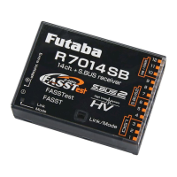
EasyManua.ls Logo

FUTABA R7014SB - User Manual

FUTABA R7014SB
2 pages
Print Icon
To Next Page IconTo Next Page
Loading...
R7014SB

FASSTest-2.4GHz Bidirectional Communication System / FASST-Multi-ch 2.4GHz
S.BUS2 / S.BUS Port and 12 Channels (+DG1,2) for Conventional System Receiver
1M23N32201

• Analog servos cannot be used with the R7014SB in the FASSTest
12CH mode.
• When the FASST Multi-ch High-speed Mode is used, analog servos
cannot be used at the CH1
6 outputs for convention systems. How-
ever, in other than the FASSTest 12CH mode, analog servos can be
used at CH7
-
12, DG1 and DG2 at any time.
Don't connect to Extra Voltage Telemetry Port before turning on a re-
ceiver.

Changesormodificationnotexpresslyapprovedbytheparty
responsibleforcompliancecouldvoidtheuserʼ sauthoritytooperatethe
equipment.
TheR7014SBreceivershouldbeprotectedfromvibrationbyfoam
rubber,Velcro,orsimilarmountingmethods.Protectfrommoisture.

Donotcutorbundlethereceiverantennawire.
Donotbendthecoaxialcable.Itcausesdamage.
Theantennasmustbemountedinsuchawaytoassuretheyarestrain
relieved.
Keeptheantennaasfarawayfromthemotor,ESCandothernoise
sourcesasyoupossiblycan.
Besurethatthetwoantennasareplacedat90degreestoeachother.
The R7014SB has two antennas. In order to maximize signal reception and
promote safe modeling Futaba has adopted a diversity antenna system. This allows
the receiver to obtain RF signals on both antennas and fly problem-free.

Youmustleave30mmatthetipoftheantennafullyexposed.The
exposedantennashouldbesecuredsothatitcannotmovearoundor
backinsideofyouraircraft.

Don'tconnectanS.BUSservo/gyrotoS.BUS2connector.
Donotconnectthepowersupplybatterytootherthanthepower
supplyconnector.
There is the danger of ignition, explosion, or burning.

Donotperformthelinkingprocedurewhilethemotor'smainpoweris
connectedortheengineisoperatingasitmayresultinseriousinjury.
Whenthelinkingiscomplete,pleasecyclethereceiverpowerand
ensurethereceiverisproperlylinkedtothetransmitter.
Pleasepowerupyoursysteminthisorder.Transmitterfirst,followed
bythereceiver.
IftheR7014SBreceiverwaspreviouslylinkedtoanothertransmitter,
makesurethattransmitterisnotoperatingwhilelinkingthereceiverto
thenewtransmitter.
56%
/LQN0RGH
VZLWFK
$QWHQQD
0RGH/('
/LQN/('
([WUD9ROWDJH
7HOHPHWU\3RUW
Thank you for purchasing a Futaba R7014SB FASSTest-2.4GHz compatible receiver.
The R7014SB receiver features bi-directional communication with a FASSTest
Futaba transmitter using the S.BUS2 port. Using the S.BUS2 port an impressive array of telemetry sensors may be utilized. It also includes both standard PWM output
ports and S.BUS output ports. The R7014SB can also be switched to the FASST-Multi-ch System.

This device complies with part 15 of the FCC Rules. Operation is subject to the following three con-
ditions:
(1) This device may not cause harmful interference, and (2) This device must accept any interference
received, including interference that may cause undesired operation.
(3) RF Exposure Information (SAR)
This device meets the government's requirements for exposure to radio waves. This device is de-
signed and manufactured not to exceed the emission limits for exposure to radio frequency (RF)
energy set by the Federal Communications Commission of the U.S. Government. The exposure stan-
GDUGHPSOR\VDXQLWRIPHDVXUHPHQWNQRZQDVWKH6SHFL¿F$EVRUSWLRQ5DWHRU6$57KH6$5OLPLW
set by the FCC is 1.6 W/kg. Tests for SAR are conducted using standard operating positions accepted
E\WKH)&&ZLWKWKH(87WUDQVPLWWLQJDWWKHVSHFL¿HGSRZHUOHYHOLQGLIIHUHQWFKDQQHOV
The FCC has granted an Equipment Authorization for this device with all reported SAR levels evalu-
ated as in compliance with the FCC RF exposure guidelines. SAR information on this device is on
¿OHZLWKWKH)&&DQGFDQEHIRXQGXQGHUWKH'LVSOD\*UDQWVHFWLRQRIZZZIFFJRYHRWHDIFFLGDIWHU
VHDUFKLQJRQ)&&,'$=356%*
The responsible party for the compliance of this device is:
)87$%$&RUSRUDWLRQRI$PHULFD
:DOO7ULDQD+Z\+XQWVYLOOH$/86$
3KRQH)$;(PDLOVHUYLFH#IXWDED86$FRP

FASSTest-2.4GHz system(14ch/12ch mode)
FASST-2.4GHz system (Multi-ch mode)
S.BUS2 and S.BUS port and Linear 12ch +Digital 2ch for conventional system
receiver
• Dual antenna diversity
• Size: 1.5 x 2 x 0.6 in. (37.0x50.2x15.9mm)
• Weight: 0.7 oz. (20.8g)
• Power requirement: 3.7V to 7.4V (Voltage range: 3.5 to 8.4V)
• Battery F/S Voltage: FASSTest:It sets up with a transmitter
FASST: 3.8V *The Battery F/S voltage is set for 4-cell NiCd/NiMH battery.
Battery F/S function doesn't work properly when other type battery is used.
• Extra Voltage port: 0V-70V DC
本產品符合低功率電波輻射性電機管理辦法 第十二條、第十四條等條文規定
1. 經型式認證合格之低功率射頻電機,非經許可,公司、商號或使用者均不得擅自變更頻率、加大功率或
變更原設計之特性及功能。
2. 低功率射頻電機之使用不得影響飛航安全及干擾合法通信 經發現有干擾現象時,應立即停用,並改善
至無干擾時方得繼續使用。前項合法通信,指依電信法規定作業之無線電通信。低功率射頻電機須忍受
合法通信或工業、科學及醫療用電波輻射性電機設備之干擾。
&+6HUYRV
'HIDXOW6%86SRUW
,WVSRVVLEOHWRFKDQJHWR'*
6%86
6%86
'*
'*

FKDQQHO
+XE
6%86HTXLSPHQW
7HOHPHWU\VHQVRU
7HOHPHWU\VHQVRU
7KHUHFHLYHUSRZHUVXSSO\FDQ
EHFRQQHFWHGWRDQ\SRUW
%DWWHU\
ۋ9
6ZLWFK
6HUYR
<KDUQHVV
:KHQDOOSRUWVDUHXVHG
90˚

(Antenna installation)


The direction of the
connectors of the
bottom 3 ports is
GLIIHUHQWE\Û

   



 
 

 

 󱐯
 
 
 
 




Question and Answer IconNeed help?

Do you have a question about the FUTABA R7014SB and is the answer not in the manual?

Summary

Usage Precautions

Servo Compatibility

Analog servos are not compatible with FASSTest 12CH mode or FASST Multi-ch High-speed mode.

Antenna Installation

Precautions for receiver antenna installation, including strain relief and placement.

Carbon Fuselage Antenna Mounting

Specific instructions for mounting antennas in carbon fiber fuselages.

Connector Insertion Safety

Guidelines for safely connecting servos, gyros, and power supplies.

Linking Procedure Safety

Safety measures to follow during the receiver-transmitter linking process.

Receiver Connection

Power and Port Connections

Details on connecting the power supply to any port and receiver setup.

Connector Orientation

Note on the 90-degree difference in orientation for bottom 3 ports.

R7014 SB Specifications

Compliance Information

System Mode Change Methods

FASSTest;FASST Change Method

Procedure to switch between FASSTest and FASST Multi-ch Normal/High-speed modes.

S.BUS;DG2 Change Method

Procedure to switch between S.BUS and DG2 modes using the SB/DG2 port.

Linking Procedures

FASSTest Linking

Steps to link the R7014SB receiver with a FASSTest transmitter.

S.BUS2 Information

Details on S.BUS2 port functionality and device compatibility.

Extra Voltage Telemetry Port

Information on connecting external voltage sensors via the telemetry port.

R7014 SB and TMA-1 Linking

Procedure for linking the receiver with a TMA-1 telemetry adapter.

FASST Linking

Steps to link the R7014SB receiver with a FASST transmitter.

Multi prop Mode Change

Procedure to switch between Multi prop modes (OFF/ON) for FASST system.

Overview

The Futaba R7014SB is a FASSTest-2.4GHz compatible receiver designed for bidirectional communication with FASSTest Futaba transmitters. It supports an impressive array of telemetry sensors through its S.BUS2 port and also features standard PWM output ports and S.BUS output ports. The R7014SB can also be switched to the FASST-Multi-ch System.

Function Description

The R7014SB receiver operates on a 2.4GHz system, offering both FASSTest (bidirectional communication) and FASST (multi-channel) modes. In FASSTest mode, it enables telemetry data transmission from connected S.BUS2 sensors back to the transmitter, providing real-time information. The receiver features dual antenna diversity to maximize signal reception and enhance safety by allowing it to obtain RF signals from both antennas. It supports 12 conventional channels, plus two digital channels (DG1, DG2), and integrates S.BUS and S.BUS2 ports for advanced servo and sensor connectivity. The receiver's power requirement ranges from 3.7V to 7.4V, with a voltage range of 3.5V to 8.4V. An Extra Voltage port is available for monitoring external battery voltage (0V-70V DC).

Usage Features

  • System Compatibility: The R7014SB is compatible with Futaba FASSTest-2.4GHz and FASST-Multi-ch system transmitters.
  • Mode Switching: The receiver can be switched between FASSTest and FASST modes.
    • FASSTest/FASST Mode Change: To change between FASSTest, FASST Multi-ch Normal, and FASST Multi-ch High-speed modes, turn on the receiver (transmitter OFF), press and hold the Link/Mode button for at least 5 seconds until the link LED blinks green/red. Release the button, then press it repeatedly to cycle through modes. Once the desired mode is reached, press and hold the button for more than 2 seconds to lock it in. After changing, cycle the receiver's power.
    • S.BUS/DG2 Port Change: To change the default S.BUS port to DG2, turn on the receiver (transmitter OFF), press and hold the Link/Mode button for at least 15 seconds until the link LED blinks red. Release the button, then press it repeatedly to cycle between S.BUS and DG2. Once the desired mode is reached, press and hold the button for more than 2 seconds to lock it in. After changing, cycle the receiver's power.
  • Linking to Transmitter (FASSTest): Bring the transmitter and receiver within 20 inches. Turn on the transmitter and place it in linking mode. Turn on the receiver. The receiver will wait for 2 seconds before attempting to link. A solid green link LED indicates successful linking. If the system type on the transmitter is changed, the receiver must be re-linked.
  • Linking to Transmitter (FASST): Bring the transmitter and receiver within 20 inches. Turn on both the transmitter and receiver. Perform the link operation using the Link/Mode switch.
  • Telemetry: In FASSTest mode, multiple optional telemetry sensors can be connected to the S.BUS2 port, and their data is displayed on the transmitter. An optional external voltage input cable (CA-RVIN-700) can be used with the Extra Voltage port to display battery voltage.
  • TMA-1 Linking (FASSTest only): To use a TMA-1 telemetry adapter, first switch the receiver to FASSTest system and link it to the transmitter. Turn off power, then turn on receiver power (transmitter off). Press the Link/Mode switch for at least 10 seconds until the link LED blinks green. The receiver enters TMA-1 linked mode, and the LED rapidly blinks red and green. Press the TMA-1 link switch until its LED starts to blink and then changes from red to green, indicating successful linking.
  • Multi Prop Mode (FASST only): To use the MPDX-1 Multi Prop Decoder, switch the receiver to FASST system (Normal or High-speed). Turn on receiver power (transmitter off). Press the Link/Mode switch for at least 10 seconds until the link LED blinks green. The receiver enters multi prop mode. Press the switch repeatedly to cycle through modes (OFF/ON). Once the desired mode is reached, press and hold the switch for at least 2 seconds until the link LED rapidly blinks red and green. Cycle the power.
  • LED Indications:
    • FASSTest Mode LED: Green Solid for receiving signals, Off for no signal/waiting for link.
    • Link LED: Red Solid for no signal/waiting for link, Green Solid for receiving signals, Green Blink for receiving signals but ID unmatched, Red Blink for waiting for link, Alternate Blink for unrecoverable error.
  • Connector Usage: The receiver power supply can be connected to any port. The direction of connectors for the bottom 3 ports is different by 90 degrees.

Maintenance Features

  • Vibration Protection: The R7014SB receiver should be protected from vibration using foam rubber, Velcro, or similar mounting methods.
  • Moisture Protection: Always protect the receiver from moisture.
  • Antenna Installation:
    • Do not cut or bundle the receiver antenna wire.
    • Do not bend the coaxial cable, as this can cause damage.
    • Mount antennas to ensure they are strain-relieved.
    • Keep antennas as far away as possible from the motor, ESC, and other noise sources.
    • Ensure the two antennas are placed at 90 degrees to each other for optimal signal reception.
  • Carbon Fuselage Antenna Installation: For carbon fuselages, leave at least 30mm of the antenna tip fully exposed. Secure the exposed antenna to prevent it from moving or retracting inside the aircraft.
  • Connector Safety:
    • Do not connect an S.BUS servo/gyro to the S.BUS2 connector.
    • Do not connect the power supply battery to any port other than the designated power supply connector to avoid ignition, explosion, or burning.
  • Linking Safety:
    • Do not perform linking procedures while the motor's main power is connected or the engine is operating to prevent serious injury.
    • After linking, cycle the receiver power to ensure proper linkage.
    • Always power up the system in this order: transmitter first, then receiver.
    • If the R7014SB was previously linked to another transmitter, ensure that the old transmitter is not operating while linking to a new transmitter.
    • In environments with many FASSTest systems, double-check that your receiver is linked to your specific transmitter to avoid linking to the wrong one.

FUTABA R7014SB Specifications

General IconGeneral
Operating voltage (max)8.4 V
Operating voltage (min)3.5 V
Quantity per pack1 pc(s)
Product typeRemote control receiver
CertificationCE
Not for children 0-3 yearsYes
Weight and Dimensions IconWeight and Dimensions
Depth50.2 mm
Width37 mm
Height15.9 mm
Weight20.8 g

Related product manuals