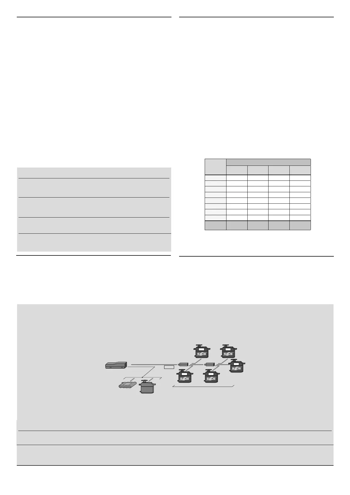
What is S.BUS?
Unlike conventional radio control systems, the S.BUS system
uses data communication to transmit control signals from a
receiver to a servo, gyro, or other S.BUS compatible device.
This data includes commands such as “move the channel 3
servo to 15 degrees, move the channel 5 servo to 30 degrees”
to multiple devices. The S.BUS devices execute only those
commands for their own set channel. For this reason, it can
be used by connecting multiple servos to the same signal
line.
[Connection by S.BUS system]
S.BUS hub S.BUS hub
S.BUS output
S.BUS
Ch output/
Battery terminal
R7008SB
Battery
S.BUS servo
Conventional
servo
1ch 3ch
2ch 5ch
4ch
3ETTHECHANNELOF
S.BUS
SERVOSBYUSINGAN
SBC-1
CHANNELCHANGER
CIU-2
53"SERIALINTERFACEORTHEPROGRAMMINGSOFTWARERESIDENTINTHE
18MZ
transmitter.
*
Can also Ee Xsed toJether Zith conventional servos HoZever conventional servos cannot Ee Xsed Ey the S.BUS oXtpXt
*
:hen XsinJ servos Zith a remote Eattery pacN Xse S.BUS HXE Zith CaEle (2Zay/remote Eattery pacN Xse)
3lease refer to the instrXction manXal of S.BUS HXE Zith CaEle (2Zay/remote Eattery pacN Xse) for the connection method
WARNING
$ONOTPERFORMTHE LINKINGPROCEDUREWHILETHEMOTORgS
MAINWIRECONNECTEDORTHEENGINEISOPERATINGASITMAY
RESULTINSERIOUSINJURY
7HENTHELINKINGISCOMPLETEPLEASECYCLETHERECEIVER
POWERANDENSURETHERECEIVERISPROPERLYLINKEDTOTHE
transmitter.
0LEASEPOWERUPYOURSYSTEMINTHISORDER4RANSMITTER
lRSTFOLLOWEDBYTHERECEIVER
FUTABA CORPORATION
1080 Yabutsuka, Chosei-mura, Chosei-gun, Chiba-ken, 299-4395, Japan
Phone: +81 475 32 6982, Facsimile: +81 475 32 6983
Link to the transmitter
Easy Link ID allows FASSTest receivers to link to compatible
transmitter without pressing the link button on the receiver.
1
"RINGTHETRANSMITTERANDTHERECEIVERCLOSETOEACHOTHER
WITHININCHESHALFMETER
2
4URNONTHETRANSMITTER0LACETHETRANSMITTERINTOTHERECEIVER
linking mode.
3
4URNONTHERECEIVER
4
4HERECEIVER WILLWAIT FOR THELINKINGPROCESSTOBEGINFOR
SECONDS &OLLOWINGTHATIT WILL RETURN TO THE NORMAL OPERATION
mode.
5
WHEN THE ,%$OF THE RECEIVER CHANGES FROM BLINKINGRED TO
solid green, linking is complete.
(!LINKWAITINGSTATEISENDEDINSECOND
s2EFERTOTHETRANSMITTERSOPERATIONMANUALFORCOMPLETEDETAILSONHOWTOPLACETHE
TRANSMITTERINTOTHELINKINGMODE
s)FTHERE ARE MANY &!334ESTSYSTEMS TURNED ON INCLOSE PROXIMITYYOURRECEIVER
MIGHTHAVEDIFlCULTYESTABLISHINGALINKTOYOURTRANSMITTER4HISISARAREOCCURRENCE
(OWEVERSHOULDANOTHER&!334ESTTRANSMITTERRECEIVERBELINKINGATTHESAMETIME
YOURRECEIVERCOULDLINKTOTHEWRONGTRANSMITTER4HISISVERYDANGEROUSIFYOUDO
NOTNOTICETHISSITUATION)NORDERTOAVOIDTHEPROBLEMWESTRONGLYRECOMMENDYOU
TODOUBLECHECKWHETHERYOURRECEIVERISREALLYUNDERCONTROLBYYOURTRANSMITTER
s )F THE 3YSTEM4YPEOF THE TRANSMITTERIS CHANGED THE RECEIVER WILL NEED TO be re-
LINKEDTOTHETRANSMITTER
Channel Modes
The R7008SB is capable of changing its channel allocations as described
in the table below. This is especially important when using the receiver
in a dual receiver mode. See your transmitter operation manual for
complete details on operating in the dual receiver mode.
1
0RESS ANDHOLD DOWNTHE ,INK-ODE BUTTONON THE23"
receiver.
2
4URNTHERECEIVERONWHILEHOLDINGDOWNTHE,INK-ODEBUTTON
!FTERPOWERUPTHEBUTTONCANBERELEASED
3
4HE ,%$ SHOULD NOW BE BLINKINGRED IN ONE OF THE PATTERNS
DESCRIBEDBYTHECHARTBELOW
4
%ACHPRESSOFTHE-ODE,INKBUTTONADVANCESTHERECEIVERTO
THENEXTMODE
5
7HENYOUREACHTHEMODETHATYOUWISHTOOPERATEINPRESS
ANDHOLDTHE-ODE,INKBUTTONFORMORETHANSECONDS
6
ONCE LOCKEDINTO THE CORRECT MODE THE ,%$ WILL CHANGE TO A
solid color.
7
PLEASECYCLETHERECEIVERSPOWEROFFANDBACKONAGAINAFTER
CHANGINGTHE#HANNEL-ODE
FASSTest
F ASSTest is a bidirectional communication system between the R7008SB
receiver and FASSTest capable transmitters. Multiple optional telemetry
sensors may be connected to the S.BUS2 on the receiver and that data is
in turn displayed on the transmitter.
0LEASESEEYOURTRANSMITTERSOPERATIONMANUALTOCONlGURETRANSMITTERTO
OPERATEWITHTELEMETRYSENSORS
S.BUS2
S.BUS2 extends S.BUS and supports bidirectional communication.
Sensors are connected to the S.BUS2 port.
/NLY3"USCAPABLEDEVICESMAYBECONNECTEDTOTHE 3"US PORT
3TANDARD3"USSERVOSANDGYROSSHOULDNOTBECONNECTEDTOTHE3"US
port.
)FTHE23"RECEIVERWASPREVIOUSLYLINKEDTOANOTHER
TRANSMITTERMAKESURETHATTRANSMITTERISNOTOPERATING
WHILELINKINGTHERECEIVERTOTHENEWTRANSMITTER
Output
connector
Channel
Mode A
1 〜 8CH
ModeB
1 〜 7CH
ModeC
9 〜 16CH
ModeD
9 〜 15CH
11199
2221010
3331111
4441212
5551313
6661414
7/B 7 7 15 15
8/SB 8 S.BUS 16 S.BUS
RedLED
blink
1time 2time 3time 4time
R7008SB CH Mode table
WARNING
4URNONTHEPOWERINTRANSMITTER → RECEIVERORDER)NADDITIONALWAYSCHECKTHEOPERATIONOFALLTHESERVOSBEFOREmIGHT
$ONOTINSERTORREMOVETHESERVOCONNECTORWHILETHERECEIVERPOWERIS/.
6ince the 6%86 servo sZitches the operation mode aXtomatically accordinJ to the type of siJnal (6%86 siJnal/3:0 siJnal) from the receiver if the connector is
inserted or removed Zhile the poZer is 21 an 6%86 connected servo Zill Ee erroneoXsly recoJni]ed and may stop
)87$%$ C25325$7,21 211 12 (1)

 Loading...