EasyManua.ls Logo

FUTABA R7008SB - User Manual

FUTABA R7008SB
2 pages
Print Icon
To Next Page IconTo Next Page
Loading...
Applicable systems: Futaba FASSTest-2.4GHz system
transmitter
R7008SB
FASSTest-2.4GHz Bidirectional Communication System
S.BUS2 / S.BUS Port and 8 Channels for Conventional System
Receiver
Compliance Information Statement
(for U.S.A.)
This device, trade name Futaba Corporation of America, model number
R7008SB, complies with part15 of the FCC Rules. Operation is subject to the
following two conditions:
(1) This device may not cause harmful interference, and
(2) This device must accept any interference received, including interference
that may cause undesired operation.
(3) This module meets the requirements for a mobile device that may be used
at separation distances of more than 20cm from human body.
To meet the RF exposure requirements of the FCC this device shall not be co-
located with another transmitting device.
The responsible party of this device compliance is:
Futaba Service Center
3002 N Apollo Drive Suite 1, Champaign, IL 61822 U.S.A.
TEL (217)398-8970 or E-mail: support@futaba-rc.com (Support)
56%6SHFLÀFDWLRQV
FASSTest-2.4GHz system(18CH/12CH mode)/S.BUS2 and S.BUS port
and 8 channels for conventional system receiver
'Xal antenna diversity
6i]e 8 [ 18 [  in (2 [  [ 1 mm)
:eiJht 8 o] (1J)
3oZer reTXirement 9 to 9(9oltaJe ranJe  to 89)
%attery )/6 9oltaJe ,t sets Xp
Zith a transmitter
([tra 9oltaJe port
9 'C
%e sXre that Zhen XsinJ (6Cs reJXlated oXtpXt the capacity of the (6C mXst
meet yoXr XsaJe condition
Thank you for purchasing a Futaba R7008SB F ASSTest-2.4GHz compatible receiver.
The R7008SB receiver features bi-directional communication
with a F ASSTest Futaba transmitter using the S.Bus2 port. Using the S.Bus2 port an impressive array of telemetry sensors may be utilized. It also
includes both standard PWM output ports and S.Bus output ports.
LED Indication
Green Red Status
Off Solid No signal reception
Solid Off Receiving signals
Alternate blink Unrecoverable error (EEPROM, etc.)
(Antenna installation)
90˚
Please refer the table below for LED status vs
receiver's condition.
10211
6%86
SRUW
6%86SRUW 6%ك
6%86ك
56%
7HUPLQDOER[
6%866HUYR
6%86*\UR
+8%
+8%
+8%
+8%
([WUD9ROWDJH
3RUW
/LQN0RGHVZLWFK
$QWHQQD
/('
6HUYRIRU FRQYHQWLRQDO
V\VWHP
&KDQQHORXWSXW
&KDQQHORXWSXW
7HPSHUDWXUH
6HQVRU
530
6HQVRU
9ROWDJH
6HQVRU
9ROWDJH
6HQVRU
$OWLWXGH
6HQVRU
$OWLWXGH
6HQVRU
6%867RRO
%DWWHU\WR%
,WLVQRWXVHGIRUDOLQN
Itconnectswiththe
batteryforpower,etc.
Externalvoltageinput
cableofanoptionis
used.Thevoltageof
thebatterycanbe
displayedwitha
transmitter.
Usage precaution
s!NALOGSERVOSCANNOTBEUSEDWITHTHE23"INTHE&!334EST
12CH mode.
s4HE23" RECEIVERCAN ONLY BE USED WITH &!334ESTCAPABLE
transmitters.
s$ONgTCONNECTTO%XTRA6OLTAGEBEFORETURNINGONARECEIVER
󾾝
WARNING
#HANGESORMODIlCATIONNOTEXPRESSLYAPPROVEDBYTHE
PARTYRESPONSIBLEFORCOMPLIANCECOULDVOIDTHEUSERS
AUTHORITYTOOPERATETHEEQUIPMENT
4HE23"RECEIVERSHOULDBEPROTECTEDFROMVIBRATION
BYFOAMRUBBER6ELCROORSIMILARMOUNTINGMETHODS
0ROTECTFROMMOISTURE
+EEPAWAYFROMCONDUCTIVEMATERIALSTOAVOID SHORT CIR-
cuits.
Antenna installation precaution
$ONOTCUTORBUNDLETHERECEIVERANTENNAWIRE
$ONOTBENDTHECOAXIALCABLE)TCAUSESDAMAGE
4HEANTENNASMUSTBEMOUNTEDINSUCHAWAYTOASSURE
THEYARESTRAINRELIEVED
+EEPTHEANTENNAASFARAWAYFROMTHEMOTOR%3#AND
OTHERNOISESOURCESASYOUPOSSIBLYCAN
"ESURETHATTHETWOANTENNASAREPLACEDATDEGREESTO
EACHOTHER
s4HE23"HASTWOANTENNAS)NORDERTOMAXIMIZESIGNALRECEPTION
AND PROMOTE SAFEMODELING &UTABA HAS ADOPTED A DIVERSITYANTENNA
SYSTEM4HISALLOWSTHERECEIVERTOOBTAIN2&SIGNALSONBOTHANTENNAS
ANDmYPROBLEMFREE
Antenna installation for carbon fuselage
󾾝
WARNING
9OUMUSTLEAVEMMATTHETIPOFTHEANTENNAFULLYEX-
POSED4HEEXPOSEDANTENNASHOULDBESECUREDSOTHATIT
CANNOTMOVEAROUNDORBACKINSIDEOFYOURAIRCRAFT
(Typical installation)

Other manuals for FUTABA R7008SB

Question and Answer IconNeed help?

Do you have a question about the FUTABA R7008SB and is the answer not in the manual?

Summary

Usage Precautions and Warnings

General Handling and Safety

Essential precautions for operating the R7008SB receiver, including servo compatibility and installation safety.

Antenna Installation Guidelines

Specific instructions and precautions for correctly installing the receiver's antennas for optimal signal reception.

Receiver Connectivity and Indicators

Extra Voltage Port Function

Details on the Extra Voltage port for power input and displaying battery voltage via transmitter.

Typical Installation Overview

Diagram illustrating the typical physical connections for servos and sensors to the receiver.

LED Status Interpretation

Explanation of the receiver's LED indications for signal reception and error states.

Compliance and Specifications

FCC Compliance Statement (USA)

Regulatory information regarding FCC compliance for the R7008SB in the United States.

R7008 SB Technical Data

Key specifications, dimensions, and power requirements for the R7008SB receiver.

Transmitter Linking and Channel Modes

Easy Link Procedure

Step-by-step guide for linking the R7008SB receiver to a compatible FASSTest transmitter.

Channel Mode Selection

Instructions for changing the receiver's channel allocation modes via the Link/Mode button.

Communication Systems

FASSTest System Overview

Explanation of the FASSTest bidirectional communication system and its use with telemetry sensors.

S.BUS System Explanation

Description of the S.BUS system for transmitting control signals to multiple servos or devices.

S.BUS2 System Features

Information on S.BUS2 extending S.BUS capabilities and supporting bidirectional sensor communication.

Safety Warnings and Best Practices

Linking Procedure Safety

Critical safety warnings regarding performing the linking procedure with the motor or engine running.

Power-Up Sequence

Recommended order for powering on the transmitter and receiver to ensure proper system initialization.

Servo Connector Handling

Precautions against inserting or removing servo connectors while the receiver power is on.

Overview

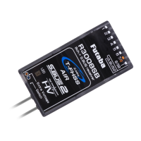
The Futaba R7008SB is a FASSTest-2.4GHz compatible receiver designed for bidirectional communication with Futaba FASSTest transmitters. It supports both the S.BUS2/S.BUS port and 8 channels for conventional system receivers, making it a versatile component for various RC applications.

Function Description:

The R7008SB receiver facilitates bidirectional communication with a FASSTest Futaba transmitter via its S.BUS2 port. This allows for the utilization of an extensive array of telemetry sensors, with data displayed directly on the transmitter. In addition to the S.BUS2/S.BUS output ports, it also provides standard PWM output ports for conventional servos. The receiver features dual antenna diversity to maximize signal reception and ensure safe modeling, allowing it to obtain RF signals on both antennas for problem-free operation.

Important Technical Specifications:

  • System Compatibility: FASSTest-2.4GHz system (18CH/12CH mode)
  • Ports: S.BUS2 and S.BUS port, 8 channels for conventional system receiver
  • Antenna System: Dual antenna diversity
  • Dimensions: 0.98 x 1.86 x 0.56 inches (24.9 x 47.3 x 14.3 mm)
  • Weight: 0.38 oz. (10.9g)
  • Power Requirement: 3.7V to 7.4V (Voltage range: 3.5 to 8.4V)
  • Battery F/S Voltage: Configurable with a transmitter
  • Extra Voltage Port: 0 ~ 70V DC

Usage Features:

The R7008SB supports Easy Link ID, allowing it to link with compatible transmitters without pressing a button on the receiver.

  1. Bring the transmitter and receiver close (within 20 inches/half meter).
  2. Turn on the transmitter and place it into the receiver linking mode.
  3. Turn on the receiver.
  4. The receiver will wait for 2 seconds for the linking process to begin, then return to normal operation.
  5. Linking is complete when the receiver's LED changes from blinking red to solid green. A link waiting state ends in 1 second.
  • Note: If multiple FASSTest systems are on nearby, the receiver might link to the wrong transmitter. Always double-check that your receiver is under the control of your transmitter.
  • If the transmitter's System Type is changed, the receiver must be re-linked.
  • Warning: Do not perform linking with the motor's main wire connected or the engine operating, as it may cause serious injury.
  • After linking, cycle the receiver power and ensure proper linkage.
  • Always power up the system in the order: Transmitter first, then receiver.
  • If the R7008SB was previously linked to another transmitter, ensure the old transmitter is not operating during the linking process to the new transmitter.

Channel Modes:

The R7008SB allows changing its channel allocations, which is crucial for dual receiver mode.

  1. Press and hold the Link/Mode button on the R7008SB receiver.
  2. Turn the receiver on while holding the Link/Mode button. Release the button after power up.
  3. The LED will blink red in one of the patterns described in the channel mode table.
  4. Each press of the Mode/Link button advances the receiver to the next mode.
  5. Once the desired mode is reached, press and hold the Mode/Link button for more than 2 seconds to lock it.
  6. The LED will change to a solid color when locked.
  7. Cycle the receiver's power off and back on after changing the Channel Mode.

S.BUS2 and S.BUS:

  • S.BUS2: Extends S.BUS capabilities by supporting bidirectional communication. Sensors connect to the S.BUS2 port, and their data is displayed on the transmitter. Only S.BUS2-capable devices should be connected to the S.BUS2 port; standard S.BUS servos and gyros should not be connected to the S.BUS2 port.
  • S.BUS: Utilizes data communication to transmit control signals from the receiver to multiple S.BUS-compatible devices (servos, gyros). Devices execute commands for their own set channel, allowing multiple servos to connect to the same signal line.
  • Setting S.BUS servo channels: Use an SBC-1 channel changer, CIU-2 USB serial interface, or the programming software in the 18MZ transmitter.
  • The R7008SB can be used with conventional servos, but conventional servos cannot be used via the S.BUS output.
  • For remote battery pack use with servos, refer to the instruction manual for the S.BUS Hub with Cable (2-way/remote battery pack use) for connection methods.
  • Warning: Always turn on the power in transmitter then receiver order, and check all servo operations before flight.
  • Warning: Do not insert or remove servo connectors while the receiver power is ON. Doing so may cause an S.BUS connected servo to be erroneously recognized and stop, as the S.BUS servo automatically switches operation mode based on the signal type (S.BUS/PWM).

Antenna Installation:

  • Precaution: Do not cut or bundle the receiver antenna wire.
  • Coaxial Cable: Do not bend the coaxial cable, as it causes damage.
  • Mounting: Antennas must be mounted to ensure strain relief. Keep them as far away as possible from the motor, ESC, and other noise sources. Ensure the two antennas are placed at 90 degrees to each other.
  • Carbon Fuselage: For carbon fuselages, leave 30mm at the tip of the antenna fully exposed. Secure the exposed antenna to prevent it from moving around or back inside the aircraft.

Maintenance Features:

Protection:

  • The R7008SB receiver should be protected from vibration using foam rubber, Velcro, or similar mounting methods.
  • Protect the receiver from moisture.
  • Keep away from conductive materials to avoid short circuits.

LED Indication:

The LED provides visual feedback on the receiver's status:

  • Green Off / Red Solid: No signal reception.
  • Green Solid / Red Off: Receiving signals.
  • Alternate blink: Unrecoverable error (EEPROM, etc.).

Compliance Information (for U.S.A.):

The Futaba R7008SB complies with part 15 of the FCC Rules.

  • Operation is subject to two conditions: (1) This device may not cause harmful interference, and (2) This device must accept any interference received, including interference that may cause undesired operation.
  • This module meets requirements for a mobile device used at separation distances greater than 20cm from the human body.
  • To meet RF exposure requirements, this device must not be co-located with another transmitting device.
  • For support, contact Futaba Service Center at 3002 N Apollo Drive Suite 1, Champaign, IL 61822 U.S.A. (TEL: (217)398-8970 or E-mail: support@futaba-rc.com).

FUTABA R7008SB Specifications

General IconGeneral
BrandFUTABA
ModelR7008SB
CategoryTransmitter
LanguageEnglish

Related product manuals