Figures & TablesFigures & Tables
Figure 3-1 Conversion of Linear Process Input --------------
Page No
7
8
10
13
14
15
23
24
24
25
27
27
28
28
29
30
31
32
33
35
37
37
39
40
42
44
45
46
9
48
4
Figure 1-1 Programming Port Location
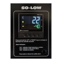
Figure 1-2 Front Panel Display
Figure 1-3 Power Up Sequence
Figure 1-4 High Limit Operation
Figure 1-5 Low Limit Operation
Figure 1-6 High/Low Limit Operation
Figure 2-1 Mounting Diagram
Figure 2-2 Lead Termination
Figure 2-3 Rear Terminal Connection Diagram
Figure 2-4 Power Supply Connections
Figure 2-5 Thermocouple Input Wiring
Figure 2-6 RTD Input Wiring
Figure 2-7 Linear Voltage Input Wiring
Figure 2-8 Linear Current Input Wiring
Figure 2-9 Event Input Wiring
Figure 2-10 Output 1 Wiring
Figure 2-11 Output 2 Wiring
Figure 2-12 RS-485 Wiring
Figure 3-2 Filter Characteristics
Figure 3-3 Normal Process Alarm
Figure 3-4 Latching Process Alarm
Figure 3-6 Remote Reset Application
Figure 3-7 Remote Lock Application
Figure 4-1 Over Temperature Protection w/ Remote Reset
Figure 5-1 Flow chart for Manual Calibration
Figure 5-2 Cold Junction Calibration Setup
Figure 5-3 RTD Calibration
Table 1-1 Display Form of Characters
Table 6-1 Input Characteristics
Figure 3-5 DC Power Supply Application
40
UM L91-Rev 8