ATTUATORI .
- PNEUMATIC ACTUATORS AND ACCESSORIES -
UsermanING ISSUE .10 March 2004
GT ATTUATORI S.r.l. REA MI 1558400 FAX (02) 90390368
V.le Europa 17 - 20090 Cusago Partita IVA e Cod.Fisc.12449540157 TEL (02) 90390322
Milan - ITALY- E-mail g.trevisan@iol.it
www.gtrevisan.it
PAG. 11 OF 20
INSTALLATION
OPERATION &
MAINTENANCE MANUAL
7.5 - When reassemble the end caps pay attention not to overturn them. Looking at the O-Ring, be
sure to place end caps with A on the top and B on the bottom.
8.0 SOLENOID VALVES SPACIFICATIONS
G.T. Attuatori solenoid valves are designed for long life, with only one part moving for commutation and
sealing of air compressed flow.
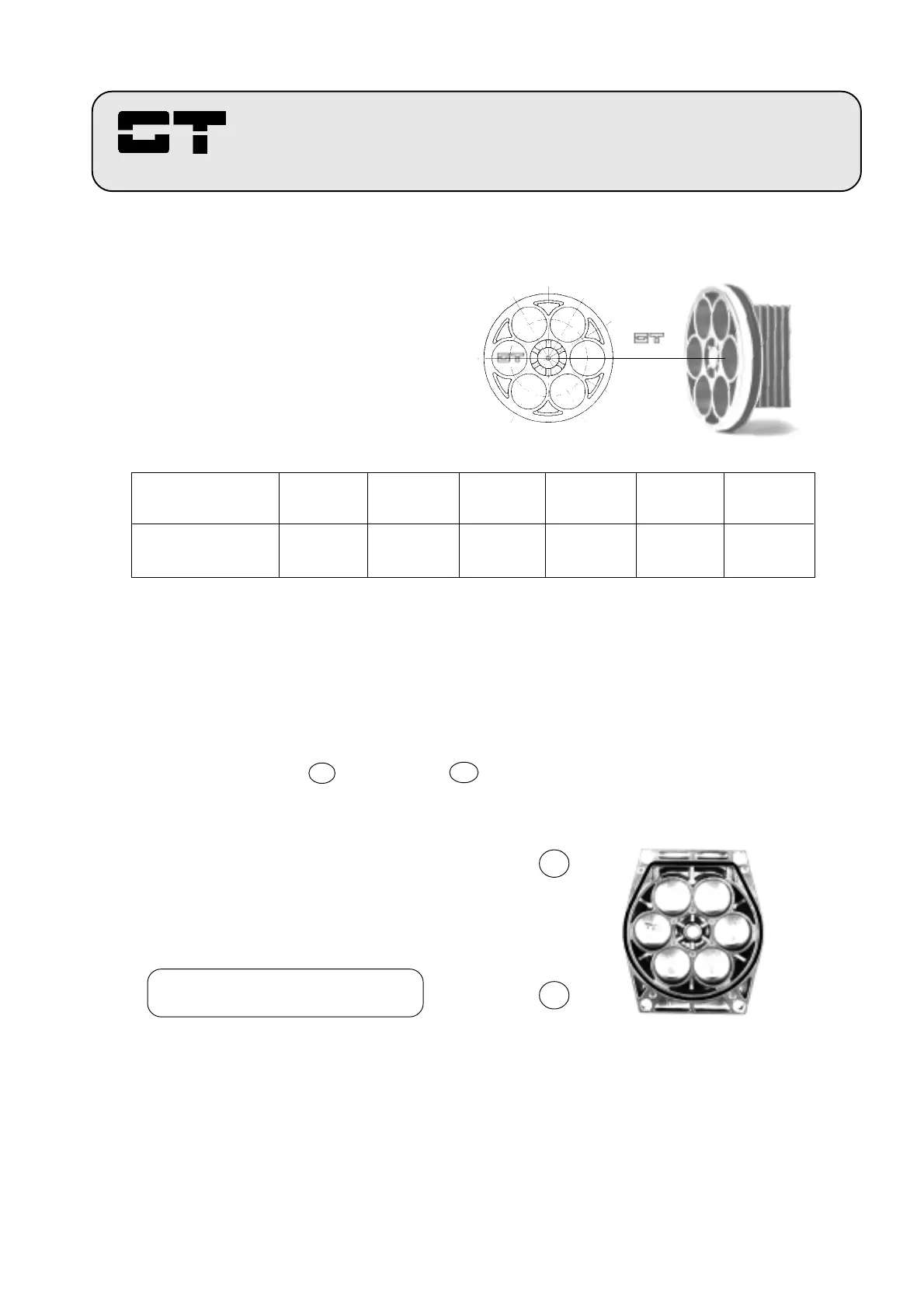
A
B
2 3
1 4
6 5
FIGURE 7
The figure shows the front view of
a piston with the cartridge spring
seats numbered, and the rack
position.
Total number of
cartridge springs
Cartridge springs All
locations. positions.
1 2 3 4 5 6
1 1 - 4 2 - 4 - 6 2-3-5-6 1-2-3-5-6
TABLE 3
Cartridge springs orientation chart.
FIGURE 8
The figure shows the internal view of
an end cap, as it must be assembled
on actuator body, with part A on the
top and the part B on the bottom.
Look at the O-Ring
Caution: with upturned end caps,
the actuator cannot operate.
 Loading...