ATTUATORI .
- PNEUMATIC ACTUATORS AND ACCESSORIES -
UsermanING ISSUE .10 March 2004
GT ATTUATORI S.r.l. REA MI 1558400 FAX (02) 90390368
V.le Europa 17 - 20090 Cusago Partita IVA e Cod.Fisc.12449540157 TEL (02) 90390322
Milan - ITALY- E-mail g.trevisan@iol.it
www.gtrevisan.it
PAG. 5 OF 20
INSTALLATION
OPERATION &
MAINTENANCE MANUAL
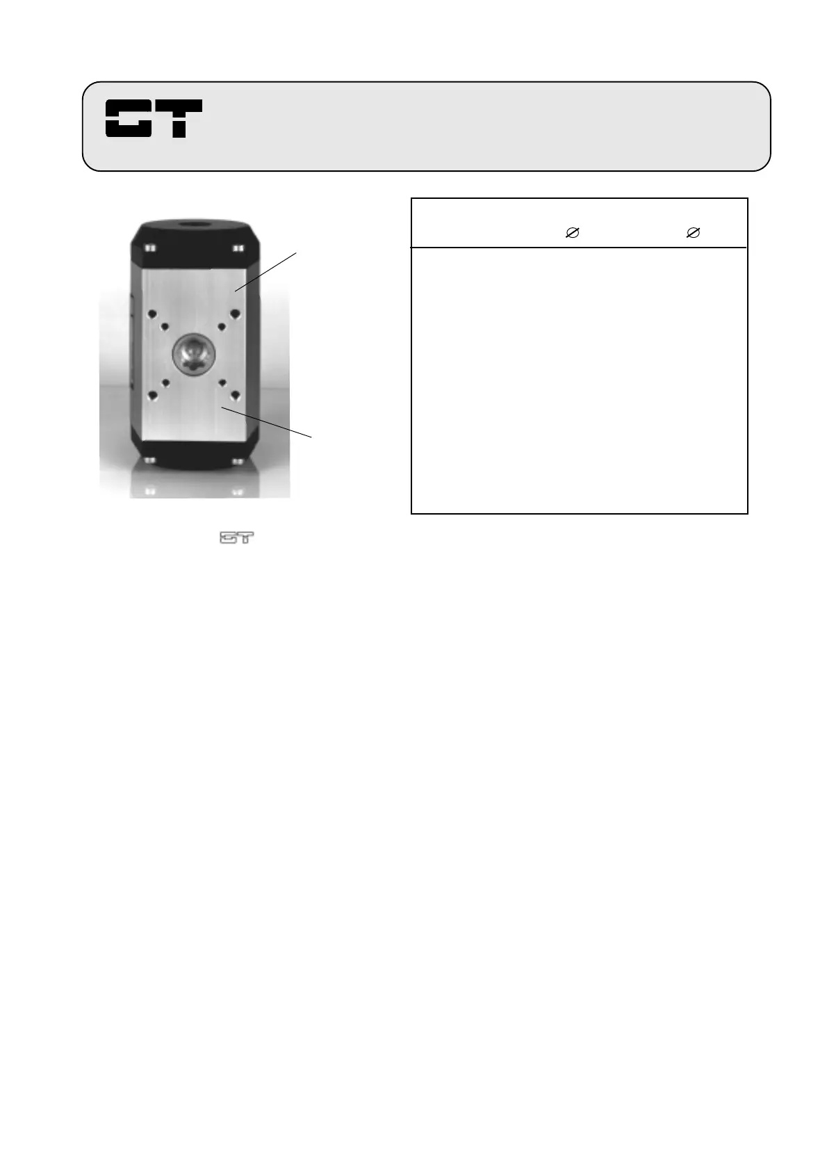
TABLE 1
ISO dimensions represents actuator
mounting bolt circles
FOR ACTUATORS INSTALLATION PLEASE FOLLOW THESE STEPS:
4.1 - Insert valve stem directly into actuator pinion, or through the coupling if necessary, to check for
proper fit.
NOTE.: If actuator is DOUBLE ACTING check to see if pinion is in the normal position, or rather in the
position necessary to get the valve closed.
4.2 - Make sure valve is in normal position before proceeding. Figure 3 describes the correct normal position
of all G.T. Componenti actuators (Including spring return types with FCW, assembling A and FCCW assembling C,
applications).
4.3 - Install mounting bracket on to valve and hand tighten all fasteners. Be sure not to fully torque bolts until
entire assembly is correctly aligned and installed.
4.4 - Place coupling on valve stem, if necessary, and position actuator on mounting brackets. Aligne valve
and actuator assembli so as to eliminate shear force on system.
Rotate the actuator to open direction (normally counter clockwise) as regards to the valve until to eliminate all
torsional play in closing direction, just to get correct closing valve position in corrispondence of actuator closing
position (piston close to piston, see figures 1A and 1C), then tighten all assembly fasteners to appropriate torque
specification given in table 3, pag. 9).
IS O
Dimension A
ISO
Dimension B
FIGURA 2
Bottom view of the actuator
with ISO standard mounting dimensions.
TIPO Dimens. A Dimens. B
ISO mm ISO mm.
GTX. 52 F03 36 F05 50
GTX. 63 F05 50 F07 70
GTX. 75 F05 50 F07 70
GTX. 83 F05 50 F07 70
GTX. 92 F05 50 F07 70
GTX.110 F07 70 F10 102
GTX.118 F07 70 F10 102
GTX.127 F07 70 F10 102
GTX.143 F10 102 F12 125
GTX.160 F10 102 F12 125
GTX.190 F14 140
GTX.210 F14 140
GTX.254 F16 165
GTX.255 F16 165
GTX.300 F16 165
 Loading...