ATTUATORI .
- PNEUMATIC ACTUATORS AND ACCESSORIES -
UsermanING ISSUE .10 March 2004
GT ATTUATORI S.r.l. REA MI 1558400 FAX (02) 90390368
V.le Europa 17 - 20090 Cusago Partita IVA e Cod.Fisc.12449540157 TEL (02) 90390322
Milan - ITALY- E-mail g.trevisan@iol.it
www.gtrevisan.it
PAG. 9 OF 20
INSTALLATION
OPERATION &
MAINTENANCE MANUAL
A
B
TABLE 3
End cap fasteners torque
specifications.
Make sure that the pistons are symmetrically placed inside the cylinder body.
In figure 4 we see that the pistons are at the mating position and are symmetrical. This is very important).
Infact, if the pistons are not tracking properly remove and reinsert them.
NOTE: Be sure that tooth engagement is even on both pistons.
6.7 - Apply equal pressure on each piston until they are fully engaged with pinion.
Rotate pinion until actuator is fully closed.
6.8 - Check the top of pinion for correct orientation. If the indicator-drive milling is perpendicular to the
cylinder body then proceed to the next part 6.9.
If the pinion is incorrectly positioned , then proceed to part 6.8b.
6.8b - Turn actuator up on its side. Rotate pinion counter clockwise until both pistons disengage from pinion.
Rotate pinion with a wrench to correct position. Apply light pressure to pistons until pinion and pistons engage.
Close actuator and check for correct pinion orientation, as at section 6. (Repeat this step as many times
as necessary to get the correct orientation).
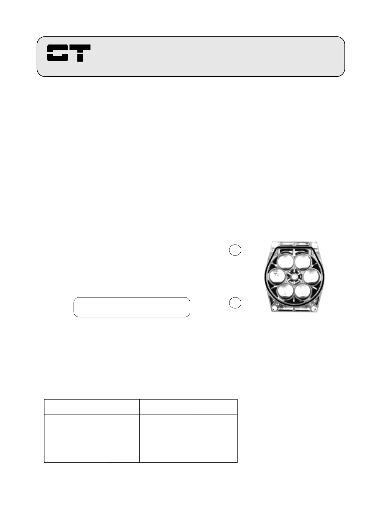
FIGURE 6
The figure shows the internal view of
an end cap, as it must be assembled
on actuator body, with part A on the
top and the part B on the bottom.
Look at the O-Ring
Caution: with upturned end caps,
the actuator cannot operate.
6.9 - In case of SPRING RETURN actuator insert cartridge springs. (For information on the loading of springs
refer to section 7.0).
6.10 - Replace end caps, being sure to position them in correct way. (See Figure 6).
N.OTE: Torque screws in alternating order to ensure that the O-Ring seats properly.
6.11 - End cap screws should be torqued, in alternating order, to the factory standard. Refer to below table 3
for correct bolt torque specifications.
ACTUATORS MODEL SCREWS TORQUE in Nm. NUT
Adjustament Nm
GTX. 52 - 63 M 5 8 2
GTX. 75 - 83 - 92 M 6 12 3
GTX.110 - 118 - 127 M 8 15 4.5
(for 127 8 Nm)
GTX. 143 - 160 M10 20 8
GTX.190 - 210 M12 28 13
GTX.254 - 255 -300 M14 40 20
(for 300 30 Nm)
 Loading...