2
ESD5300 Speed Control Unit 09-2020-H PIB1041
Governors America Corp. © 2020 Copyright All Rights Reserved
3
INSTALLATION
The ESD5300 speed controller can be placed in a control cabinet or engine mounted enclosure with other control equipment. If water,
mist, or condensation can come in contact with the controller, it should be mounted vertically, to allow any accumulated uids to drain
away from the unit.
WIRING
4
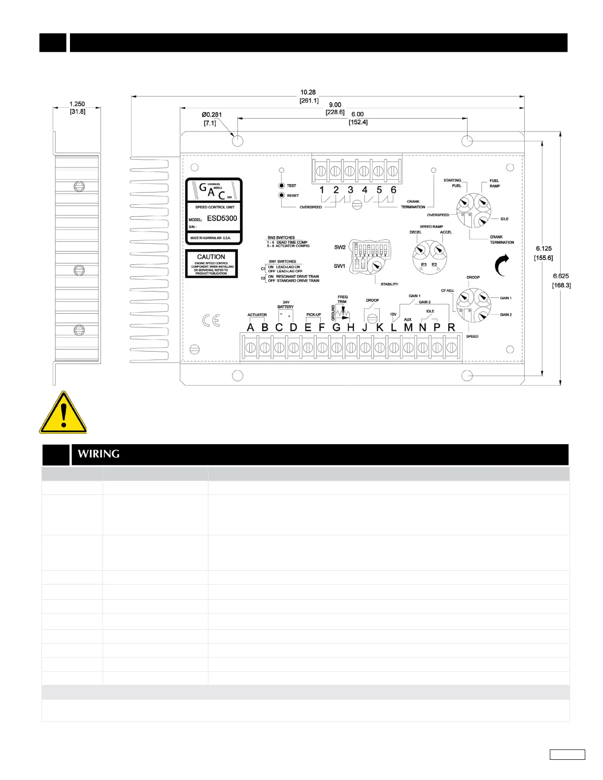
TERMINAL DEFINITION NOTES
A & B
Actuator (+/-)
14 AWG wire
C & D Battery Power (-/+)
• 14 AWG wire
• 20 amp fuse must be installed in the positive battery lead to protect against any overload or
short circuit
• Battery positive (+) input is Terminal D
E & F
Magnetic Pickup
(- is ground)
• Wires must be twisted and/or shielded for their entire length
• Gap between speed sensor and gear teeth should not be smaller than 0.02 in. (0.45mm)
• Speed sensor voltage should be at least 1.0 V AC RMS during crank
G Ground Signal
H Frequency Trim Shielded cable required for lengths over 15 ft (5 m) and connected to Terminal G
J & K Droop Active when closed
L & R Gain 1 & Gain 2 Gain 1 when open / Gain 2 when closed
M Aux Input Load Sharing / Synchronizing, Ground at Terminal G
N & P Idle Active when closed
1 - 6 Overspeed Relay Contacts
5 - 6 Crank Relay Contacts Active when closed
RECOMMENDATIONS
1. Shielded cable should be used for all external connections to the ESD control.
2. One end of each shield, including the speed sensor shield, should be grounded to a single point on the ESD case.
An overspeed shutdown device, independent of the governor system, must be provided to prevent loss of engine control
which may cause personal injury or equipment damage. Do not rely exclusively on the governor system to prevent over-
speed. A secondary shuto device such as a fuel solenoid must be used.
 Loading...