EasyManua.ls Logo

GAC ESD5500E Series - User Manual

GAC ESD5500E Series
9 pages
Print Icon
To Next Page IconTo Next Page
Loading...
1
Governors America Corp. © 2020 Copyright All Rights Reserved
ESD5500E Series Speed Control Unit 9-2020-F PIB1002
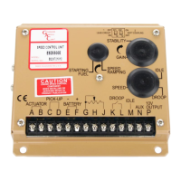
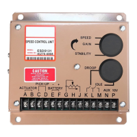
ESD5500E Series
Speed Control Unit
1
2
INTRODUCTION
SPECIFICATIONS
PERFORMANCE
Isochronous Operation ± 0.25 % or better
Speed Range / Governor
1 - 7.5 kHz Continuous
Speed Drift with Temperature
±1 % MAX
Idle Adjust Clockwise 60 % of Set Speed
Idle Adjust Counterclockwise Less than 1200 Hz
Droop Range 1 - 5 % regulation
Droop Adjust Maximum
(K-L jumpered)
400 Hz ±75 Hz per 1.0 A change
Droop Adjust Minimum
(K-L jumpered)
15 Hz ±75 Hz per 1.0 A change
Speed Trim Range ± 200 Hz
Remote Variable Speed
Range
500 - 7.5 kHz
Terminal Sensitivity
J
L
N
P
100 Hz ±15 Hz/Volt @ 5.0 kΩ Impedance
735 Hz ±60 Hz/Volt @ 65.0 kΩ Impedance
148 Hz ±10 Hz/Volt @ 1 MΩ Impedance
10 V DC Supply @ 20 mA MAX
INPUT / OUTPUT
DC Supply 12 V DC and 24 V DC Battery Systems
Transient and Reverse Voltage Protected*
Polarity Negative Ground (Case Isolated)
Power Consumption 50 mA continuous plus actuator current
Speed Signal Range
Speed Sensor Signal
1.0 - 50 V AC
1.0 - 120 V RMS
Actuator Current Range**
(77°F (25°C))
Minimum 1.0 A
Nominal 7.0 A
Peak 10.0 A
The ESD5500E Series Speed Control Unit is an all-electronic device designed to control
engine speed quickly and precisely in response to transient load changes.
The ESD5500E controls a wide variety of engines in isochronous or droop mode when
connected to a proportional electric actuator and magnetic speed sensor. The ruggedly
built ESD5500E series is designed to withstand the engine environment. Light-Force
variations are available.
MODEL DESCRIPTION
ESD5500E Multi-VDC / Standard Unit
ESD5520E Multi-VDC / Light-Force (Low-Current Optimized PID) / Enhanced Droop
ESD5522E
Multi-VDC / Light-Force (Low-Current Optimized PID) / Enhanced Droop
for Cummins EFC Forward Acting (Normally Closed)
ESD5526E
Multi-VDC / Light-Force (Low-Current Optimized PID) / Anti-Windup
Circuit (Gaseous) / Recommended for T1/T2 ATBs
ESD5528E
Multi-VDC / Anti-Windup Circuit (Gaseous) / Recommended for T3/T4
ATBs
RELIABILITY
Vibration 1 g @ 20-100 Hz
Testing 100 % Functionally Tested
ENVIRONMENTAL
Ambient Temperature -40° to 85 °C (-40° to 180 °F)
Relative Humidity up to 95 %
All Surface Finishes Fungus Proof, Corrosion Resistant
COMPLIANCE / STANDARDS
Agency CE (EN55011, EN50081-2, EN50082-2),
RoHS, Lloyds Register,
DNV/GL, Bureau Veritas
PHYSICAL
Dimension See Wiring Diagram and Outline
Weight 1.20 lbf (0.54 kgf)
Mounting Any position, vertical preferred
* Protected against short circuit to actuator (shuts o󰀨 current to actuator), unit automatically turns on when short is removed.
** Protected against reverse voltage by a series diode. A 15 A fuse must be installed in the positive battery lead.

Questions and Answers

  • R
    Ryan CastanedaAug 4, 2025
    Why is my GAC ESD5500E engine governing system not functioning?
    • M
      Melanie Decker DVMAug 5, 2025
      If the GAC Control Unit's engine governing system isn't working, start by checking the DC battery power connection and the fuse. Also, ensure the battery voltage is adequate and inspect the wiring for errors. Perform voltage tests as described in Steps 1 through 4. If the problem persists, consult your actuator publication for actuator testing procedures.
  • E
    Emily AndersonAug 10, 2025
    What to do if GAC ESD5500E shows fast periodic instability?
    • J
      James BensonAug 10, 2025
      If your GAC Control Unit is showing fast periodic instability, ensure switch C1 is set to OFF. Readjust the GAIN and STABILITY for optimum control. Try removing the E1 to E2 jumper and readjust GAIN and Stability afterward. Also, turn off any other electrical equipment that might be causing interference.
  • A
    Alexander CooperAug 17, 2025
    How to fix slow periodic instability in GAC Control Unit?
    • A
      Alicia LyonsAug 17, 2025
      To address slow periodic instability in your GAC Control Unit, readjust the GAIN and STABILITY. Additionally, adjust the DEAD TIME COMPENSATION by adding a capacitor from posts E2 to E3 (negative on E2), starting with 10 mF and increasing until the instability is eliminated. Check the fuel system linkage during engine operation for binding, high friction, or poor linkage.
  • J
    John ReeseAug 23, 2025
    What causes non-periodic engine behavior in GAC ESD5500E?
    • K
      kellyrichardAug 23, 2025
      To resolve non-periodic engine behavior with your GAC Control Unit, increasing the GAIN may reduce the instability, but not totally correct it. Check for engine mis-firings, an erratic fuel system, or load changes on the generator set voltage regulator. If the throttle is slightly erratic but performance is fast, move switch C1 to the OFF position.
  • D
    dannybryanAug 28, 2025
    How to increase magnetic speed signal in GAC ESD5500E?
    • R
      Rebecca Stewart MDAug 28, 2025
      To increase the magnetic speed signal in your GAC Control Unit, raise the amplitude of the speed sensor signal by reducing the gap between the speed sensor tip and the engine ring gear.

Summary

INTRODUCTION TO ESD5500 E SERIES

Overview and Purpose

All-electronic device for engine speed control responding to transient load changes.

Key Specifications Summary

Details performance, reliability, environmental, compliance, physical, and I/O parameters.

INSTALLATION AND WIRING GUIDELINES

Installation Diagram and Recommendations

Includes outline diagram, dimensions, and mounting advice.

Wiring Practices and Terminals

Covers shielded cables, terminal assignments, and special wiring configurations.

ENGINE STARTUP AND ADJUSTMENTS

Pre-Startup Settings and Stability Tuning

Covers initial settings for GAIN, STABILITY, STARTING FUEL, and SPEED RAMPING.

OPERATION AND STARTING FUEL

Starting Fuel Adjustment Procedure

Procedure to minimize exhaust smoke at start-up.

Methods of Operation

Describes two methods: Operating Speed and Idle Speed.

ADDITIONAL FEATURES AND ACCESSORIES

Idle Speed and Coupling Controls

Features for idle speed setting and soft/lead coupling circuits.

Accessory Input and Supply

Details for load sharing units, auto synchronizers, and accessory power.

VARIABLE SPEED AND DROOP OPERATION

Remote Variable Speed Control

Using a potentiometer to adjust engine speed continuously over a range.

Speed Droop Operation

Function and adjustment of droop for paralleling generators.

TROUBLESHOOTING

System Inoperability and Speed Signal Issues

Diagnosing system failure and insufficient magnetic speed signals.

Instability Diagnosis

Identifying and resolving fast, slow, and non-periodic engine instability.

UNSATISFACTORY PERFORMANCE ISSUES

Overspeed and Actuator Problems

Troubleshooting engine overspeed and actuator energization issues.

Low Engine Speed Issues

Diagnosing why the engine remains below the desired governed speed.

GAC ESD5500E Series Specifications

General IconGeneral
Isochronous Operation Range±0.25% or better
Speed Range1K ~ 7.5K Hz continuous
Droop Range1 ~ 5%
Operating Temperature Range-40 ~ 85 °C
Input Power12 or 24 VDC Battery Systems (Transient & Reverse Voltage Protected)
Reverse Polarity ProtectionYes

Related product manuals