3
Governors America Corp. © 2020 Copyright All Rights Reserved
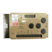
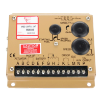
ESD5500E Series Speed Control Unit 9-2020-F PIB1002
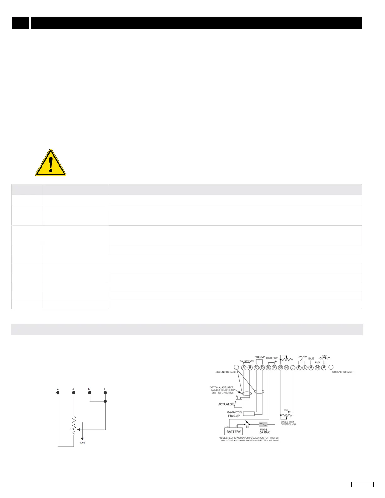
TERMINAL DEFINITION NOTES
A & B Actuator (+/-) 16 AWG (1.3mm
2
) or larger wire
C & D
Magnetic Speed Pickup
(D is ground)
• Wires must be twisted and/or shielded for their entire length
• Gap between speed sensor and gear teeth should not be smaller than 0.02 in. (.51mm)
• Speed sensor voltage needs to be at least 1 V RMS during crank
E & F Battery Power (-/+)
• 16 AWG (1.3mm
2
) or larger wire
• A 15 A fuse must be installed in the Positive battery lead to protect against reverse voltage
• Battery positive (+) input is Terminal F
G Ground Signal
H For 12 V systems with actuator currents above 5 A, may sometimes require a jumper between Terminals H and G
J Variable Speed 5 kΩ resistive nominal.
K & L Droop Select Active when closed
M Idle Select Close for Idle
N Accessory Input Load Sharing/Synchronizing, 0-10 V DC (5V Nominal, Reversed, 148 Hz/V). Shielded cabling recommended.
P Accessory Power Supply 10 V DC Output To Power GAC Load Sharing and Synchronizing Modules
When wiring ESD5500E Series controllers:
1. Use shielded cable for all external connections to the ESD controller.
2. One end of each shield, including the speed sensor shield, should be grounded to a single point on the ESD case.
3. Terminal A, B, E,and F should be 16 AWG or larger. Long cables require increased wire size to minimize voltage drops.
4. Battery positive (+) Terminal F should be fused for 15 A.
5. Magnetic speed sensors Terminals C and D must be twisted and or shielded for the entire length.
6. The gap between the speed sensor and the ring gear teeth should be smaller than 0.02 in [0.5 mm] usually backing out 3/4 turn after
touching ring gear teeth. Speed sensor voltage should be at lease 1 V AC RMS during cranking.
7. If auto synchronization is used alone, not with a load sharing module, use a 3 Ω resistor between Terminal N and P to match the voltage
between the speed control unit and the synchronizer.
8. When operating at the upper end of the control unit frequency range, add a jumper wire between Terminal G and J to increase the fre-
quency range of the control unit over 7000 Hz.
9. Terminal P is used to supply +10 V DC regulated supply to accessories. No more than 20 mA of current can be drawn from this supply.
Ground reference is Terminal G. A short circuit in this terminal can damage the speed control unit.
4
WIRING (CONTINUED)
An overspeed shutdown device, independent of the governor system, must be provided to prevent loss of
engine control which may cause personal injury or equipment damage. Do not rely exclusively on the governor
system to prevent overspeed. A secondary shuto device such as a fuel solenoid must be used.
ADDING A POTENTIOMETER
Use a single remote speed adjustment potentiometer to adjust engine
speed. Select the desired speed range and the corresponding potenti-
ometer value. If the exact range is not found select the next higher range
potentiometer. Connect the potentiometer as shown in the potentiometer
diagram.
 Loading...