5
ESD5300 Speed Control Unit 09-2020-H PIB1041
Governors America Corp. © 2020 Copyright All Rights Reserved
A strip chart recorder can be used to further optimize the adjustments. If further performance improvements are required,
See Section 10, System Troubleshooting, for more information.
8
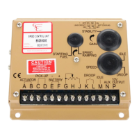
INITIAL ADJUSTMENTS
Once the engine is running at operating speed and at no load, the following governor performance adjustment can be made to increase
engine stability.
PARAMETER ADJUSTMENT PROCEDURE
P
(GAIN)
1.
2.
3.
4.
Rotate the GAIN adjustments CW until instability develops.
Gradually move the adjustment CCW until stability returns.
Move the adjustment one division further CCW to ensure stable performance.
If instability persists, adjust the next parameter.
I
(STABILITY)
1.
2.
Follow the same adjustment procedure as the P parameter using the Stability potenti-
ometer.
If instability persists, adjust the next parameter.
D
(DEADTIME)
1. Follow the instability procedure in Section 10, System Troubleshooting.
NOTE
ADDITIONAL FEATURES
9
Many applications require a exible coupling between the engine and its load. This can take the
form of a soft rubber segmented coupling or a drive shaft which behaves as a natural spring.
These couplings are used for alignment purposes, torsional considerations, or due to excess
length of the drive shaft. When a drive train produces a resonant device causing variable loads
at a cylindrical rate to be placed on the engine and its ywheel, this can cause excessive throttle
movement at the same frequency as the resonance. The ESD5300 speed control unit has a
special circuit, SOFT COUPLING, that minimizes the oset on the resonances on the governor.
If the system exhibits these resonance characteristics, set dip switch SW1, C2 to
ON to activate soft coupling. Readjust the control system per the procedure in Sec-
tion 8, Adjustments, and the result should be a signicant reduction in throttle dither.
Although the governor does not respond to the resonance any longer does not mean the reso-
nance is not still present in the drive train.
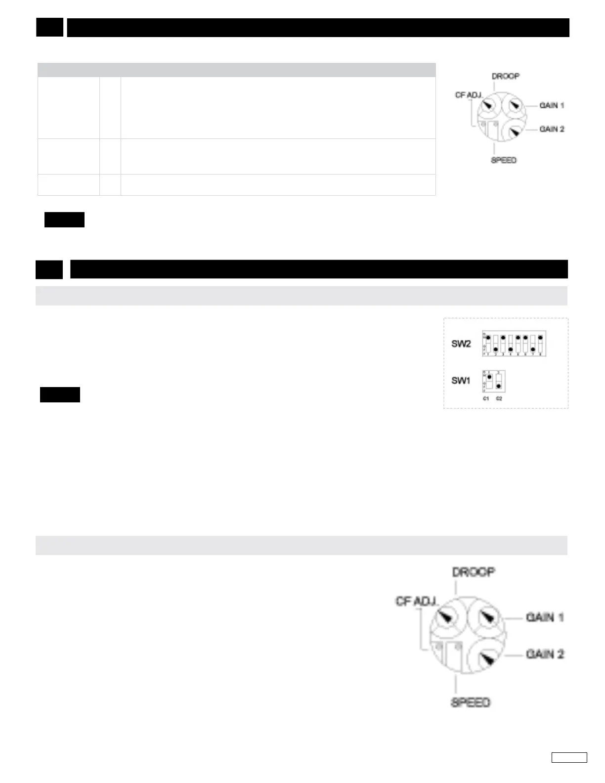
If droop operation is desired (speed setting reduces with increased engine load), close the
switch contact across Terminals J and K.
Rotate the DROOP adjustment CW to increase the droop percentage 0 setting (Full CCW)
= Zero droop. 100 = maximum droop.
SOFT COUPLING / RESONANT DRIVE TRAINS
SPEED DROOP OPERATION
NOTE
 Loading...