9
ESD5300 Speed Control Unit 09-2020-H PIB1041
Governors America Corp. © 2020 Copyright All Rights Reserved
If unsuccessful in solving instability, contact GAC for assistance.
info@governors-america.com or 413-233-1888
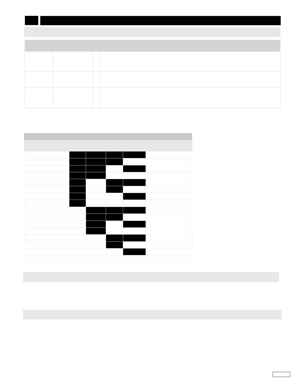
SW2 SWITCH SETTINGS FOR INSTABILITY
SLOW INSTABILITY
SEQUENCE
SW2-1 SW2-2 SW2-3 SW2-4
FAST INSTABILITY
SEQUENCE
1 ON ON ON ON 16
2 ON ON ON OFF 15
3 ON ON OFF ON 14
4 ON ON OFF OFF 13
5 ON OFF ON ON 12
6 ON OFF ON OFF 11
7 ON OFF OFF ON 10
8 ON OFF OFF OFF 9
9 OFF ON ON ON 8
10 OFF ON ON OFF 7
11 OFF ON OFF ON 6
12 OFF ON OFF OFF 5
13 OFF OFF ON ON 4
14 OFF OFF ON OFF 3
15 OFF OFF OFF ON 2
16 OFF OFF OFF OFF 1
The speed control unit will govern well with 1.0 V AC RMS speed sensor signal. A speed sensor signal of 3 V RMS or greater at
governed speed is recommended. A strong magnetic speed sensor signal will eliminate the possibility of missed or extra pulses. The
amplitude of the speed sensor signal can be raised by reducing the gap between the speed sensor tip and the engine ring gear. The
gap should not be any smaller than 0.020 in (0.45 mm). When the engine is stopped, back the speed sensor out by 3/4 turn after
touching the ring gear tooth to achieve a satisfactory air gap.
INSTABILITY SYMPTOM
PROBABLE CAUSE OF
ABNORMAL READING
Fast Insta-
bility
An irregularity of
speed above 3Hz.
(Perceived as a
jitter)
1.
2.
3.
Set SW1 C1 to OFF (Lead/Lag) and/or set SW2 switches 1,2, and 3 to ON (DTC).
If instability continues set SW1 C2 (Soft Coupling Filter) to ON.
If instability continues turn o battery changers or other electrical equipment to see if the symptom
disappears.
Slow Periodic An irregularity of
speed below 3Hz.
(Sometimes severe)
1.
2.
Set SW1 C1 (Lead/Lag) to ON.
If instability continues set SW2 switches (DTC) to the ON/OFF positions in the sequential order de-
scribed in the
SW2 SWITCH SETTINGS FOR INSTABILITY table.
Slow Periodic
(continued)
An irregularity of
speed below 3Hz.
(Sometimes severe)
1. If slow stability is unaected by the explained procedure above, add a small amount of droop.
Additional Dead Time Control can be added by connecting a capacitor across the two posts below the
ACCEL/DECEL adjustments. The positive side (+) of the cap is to be connected to E3. 20 MFD and
above should be used.
For slow instability use the table below to set the SLOW INSTABILITY SEQUENCE and for fast instability use the FAST INSTABILITY
SEQUENCE. Start by setting the switches to reect Sequence 1. If instability persists, adjust the switches to reect Sequence 2.
Continue through each sequence until instability stops.
10
SYSTEM TROUBLESHOOTING (CONTINUED)
INSTABILITY
INSUFFICIENT MAGNETIC SPEED SIGNAL
EMI SUSCEPTIBILITY
The governor system can be adversely aected by large interfering signals that are conducted through the cabling or through direct
radiation into the control circuits. All GAC speed control sensors contain lters and shielding designed to protect the units sensitive
circuits from moderate external interfering sources.
If it is suspected that external elds, either those that are radiated or conducted, are or will aect the governor systems operation, it is
recommended to use shielded cable for all external connections. Be sure that only one end of the shields, including the speed sensor
shield, is connected to a single point on the case of the speed control unit. Mount the speed control to a grounded metal back plate
or place it in a sealed metal box.
 Loading...