T
T
F
F
-
-
D
D
G
G
C
C
A
A
L
L
-
-
P
P
A
A
K
K
F
F
i
i
x
x
t
t
u
u
r
r
e
e
M
M
a
a
n
n
u
u
a
a
l
l
MIC TRAC MT-3000
15
2010 Gagemaker, LP
RCDMMT300010-10
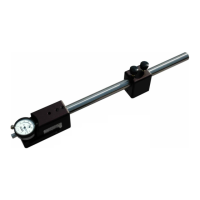
16. Turn the Y axis adjust knob counterclockwise
until the depth micrometer rod contacts the flat
face anvil.
16. Enter the gage measurements in the Measured
column as follows:
• Continue turning the Y axis adjust knob
until the X axis moves approximately ½
inch. Secure Locks 1 and 2.
• Click the Add Value button.
17. Then, using each master value, continue
measuring the depth micrometer until the
values for the first depth rod are recorded in
CERTIFI.
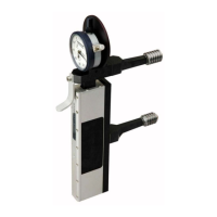
18. Loosen Lock 1 and 2 and turn the Y axis adjust
knob clockwise to slide the Y axis to the right.
Note: It is recommended that depth rods 6” and
longer be supported during calibration.
19. Locate the depth gage support. With the
thumbscrew facing forward, slide the support
over the left flat face anvil.
20. Remove the depth rod from the depth
micrometer and insert the next depth rod.

 Loading...