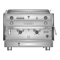
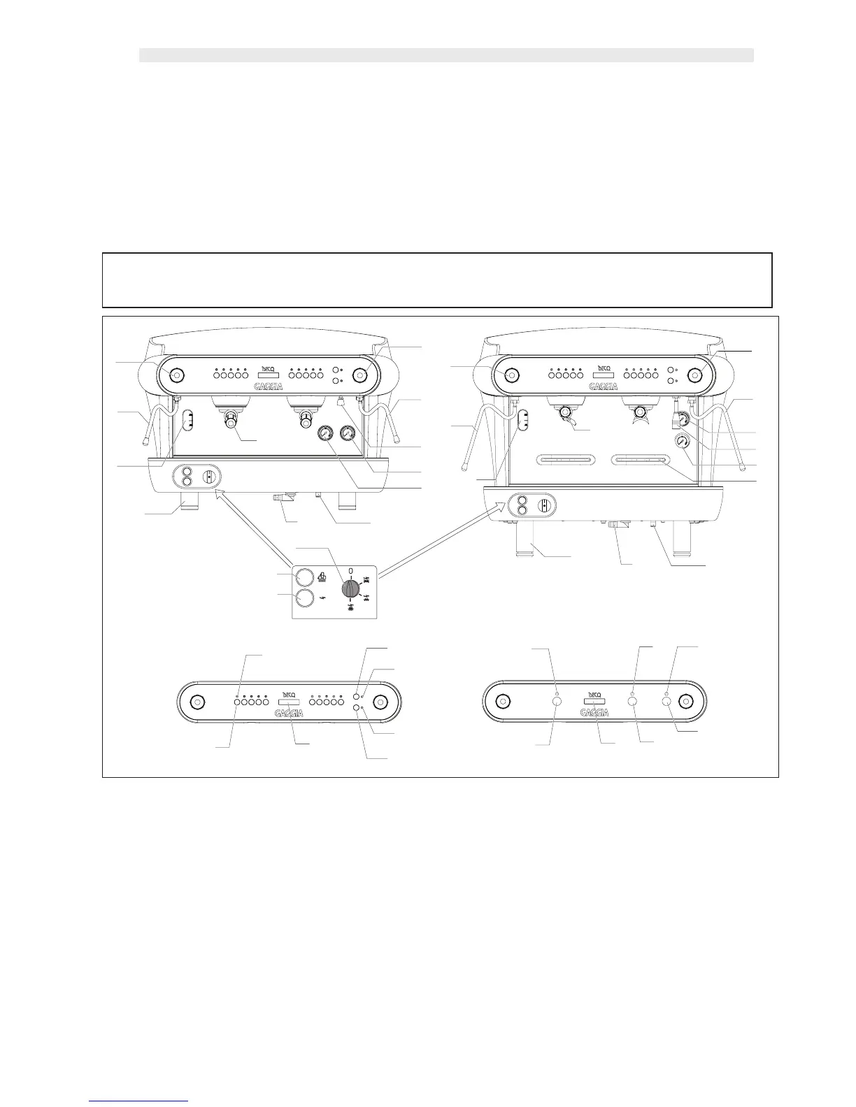
1 BOILER FILLING VALVE
2 DISCHARGE PIPE
3 MACHINE ON WARNING INDICATOR
4 CUP WARMING SWITCH
5 MAIN DISCONNECTING SWITCH
6 ADJUSTABLE SUPPORT
7 BOILER LEVEL INDICATOR
8 LEFT STEAMER VALVE
9 LEFT STEAMER PIPE
10 PUMP PRESSURE GAUGE
11 BOILER PRESSURE GAUGE
12 HOT WATER DELIVERY PIPE
13 RIGHT STEAMER VALVE
14 RIGHT STEAMER PIPE
15 DELIVERY INDICATOR LED
16 CONTROLS KEYBOARD
17 DISPLAY
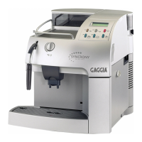
18 WATER DELIVERY BUTTON 1
19 WATER DELIVERY INDICATOR LED 1
20 WATER DELIVERY BUTTON 2
21 WATER DELIVERY INDICATOR LED 2
22 COFFEE DELIVERY BUTTON
23 COFFEE DELIVERY INDICATOR LIGHT
24 WATER DELIVERY BUTTON
25 WATER DELIVERY INDICATOR LIGHT
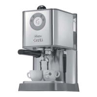
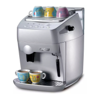
26 FILTER HOLDER BOWL
27 ADDITIONAL ESPRESSO GRILL
Connect to an earthed socket that complies with the appli-
cable regulations.
Verify that the power supply cable is undamaged and com-
plies with National and European safety standards.
The user is responsible for supplying electric power to the
machine and protecting the power line using an adequate
safety disconnecting switch (cut out switch) in compliance
with the regulations applicable in the country where the
machine is to be installed.
Connect the power supply cable (I) to the mains supply
using a plug, or a multi-pole disconnecting switch must be
foreseen with a contacts distance of at least 3 mm in the
case of a fixed installation, (D) to separate the mains supply.
Refer to the diagram shown on the box containing the main
disconnecting switch in order to change the voltage.
Connecting the yellow/green coloured wire to the earthing
system of the premises is a COMPULSORY requirement.
fig. 3
12
6
3
4
5
7
8
9
10
11
12
13
14
18
19
15
21
20
17
16
17
22
23
25
23
22
24
Model. D
Model. E
26
8
9
7
6
2
1
13
14
11
10
12
26
27