EasyManua.ls Logo

Gaggia Anima User Manual

Gaggia Anima
59 pages
To Next Page IconTo Next Page
Page #1 background imageLoading...
Page #1 background image
All parts of this document are the property of Philips.
All rights reserved.  is document and all the information herein is provided without liability deriving from any errors or omissions. Furthermore, no part may be reproduced, used or
collected, except where express authorisation has been provided in writing or through a contractual agreement.
Published by Philips
Subject to modi cation EN 4219 400 00033
Service
Service
Service
Service
Co ee Machine
Gaggia Anima
2015-July-30
Service
Service
Manual
Manual
Rev. 00 July 2015
General Information
Description Value
Housing material Thermoplastic type
Size (w x h x d) Anima OTC AMF CMF 221 x 340 x 430 mm (data may vary depending on the model)
Size (w x h x d) Anima XL 221 x 386 x 430 mm
Weight OTC AMF CMF 7,5 kg (data may vary depending on the model)
Weight Anima XL 8 kg
Power cord length 800 - 1200 mm
Control panel Front type
Cup size Up to 152 mm
Water tank OTC AMF CMF 1.8 litres - Removable type
Water tank Anima XL 2.5 litres - Removable type
Coffee bean hopper capacity Anima OTC AMF CMF 250 g
Coffee bean hopper capacity Anima XL
500 g
Coffee grounds drawer capacity 15
Milk carafe capacity 0,5 l (OTC version)
Pump pressure 15 bar
Boiler Stainless steel boiler
Safety devices Thermal fuse
Energy saving mode < 1 Wh
Nominal voltage - Power rating - Power supply Read the data plate placed inside the service door
Question and Answer IconNeed help?

Do you have a question about the Gaggia Anima and is the answer not in the manual?

Gaggia Anima Specifications

General IconGeneral
Product typeEspresso machine
Capacity in cups- cups
Coffee input typeCoffee beans, Ground coffee
Coffee maker typeFully-auto
Country of originItaly
Appliance placementCountertop
Water tank capacity1.8 L
Coffee beans capacity250 g
Maximum operating pressure15 bar
Number of grinder settings5
Reservoir for brewed coffeeCup
Number of temperature settings3
Adjustable coffee spout height range110 - 150 mm
Control typeButtons
Display typeLCD
Product colorBlack
Housing materialAcrylonitrile butadiene styrene (ABS), Stainless steel
Multi beverage-
Quantity per pack1 pc(s)
AC input voltage230 V
AC input frequency50 Hz
Power consumption (standby)1 W
Weight and Dimensions IconWeight and Dimensions
Depth430 mm
Width221 mm
Height340 mm
Weight7900 g

Summary

Introduction to Coffee Machine Service

Documentation Requirements

Lists necessary documents for repair procedures.

Tools and Equipment Required

Specifies required tools and test equipment for maintenance.

Materials Required for Service

Lists recommended materials and consumables for servicing.

General Safety Warnings

Crucial safety precautions for appliance repair and handling.

Service Policy Guidelines

Outlines policy for in-warranty repairs and component usage.

Coffee Machine Technical Specifications

General Technical Specifications

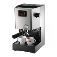
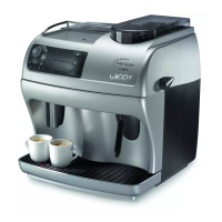
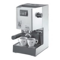
Overview of power, dimensions, weight, and capacities.

Coffee Product Temperature Measurement

Guidelines for measuring coffee temperature accuracy.

Milk Product Temperature Measurement

Procedures for evaluating milk temperature and cream height.

Machine Parameters and Performance

Details on product quantities, descaling, and performance metrics.

User Operation and Maintenance

Customer Menu and Settings

Explains user-adjustable settings and programming menu.

Operation, Cleaning, and Maintenance

Guides on daily use, cleaning routines, and basic maintenance.

Coffee Machine Operating Logic

Water Circuit Operation

Diagram and explanation of the water flow path.

Milk Carafe Mechanism

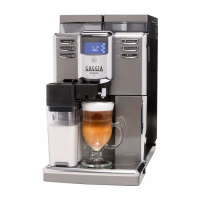
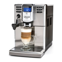
Details on the milk frothing and dispensing system.

Key Component Functions

Operation of microswitch, temperature sensor, and gear motor.

Coffee Grinder and Dosing Systems

Operation, adjustment, and error detection for the coffee grinder.

Brewing Cycle and Water System Management

Explains brewing cycle, water level, descaling, and filter functions.

Troubleshooting and Error Codes

Test Mode Procedures

Guide to entering and navigating diagnostic test modes.

Diagnostic Error Codes

Lists error codes, their causes, and suggested actions.

Standard Checks and Maintenance

Repair Schedule Actions

Steps involved in a typical repair process.

Service Schedule Components

Components and actions for routine service.

Final Test Procedures

Checks performed after repair or servicing.

Machine Disassembly Procedures

Outer Casing and Shell Removal

Instructions for removing external covers and panels.

Dispenser and Grinder Component Servicing

Steps to disassemble dispenser, grinder, and blades.

Fluid System Components

Procedures for removing boiler, pump, flow meter, etc.

Electronic Boards and Interface

Steps to access and remove CPU board, interface, and programming access.

Clamp Fittings and Removal

Guidance on fitting and removing Oetiker clamps.

Additional Information and Notes

Water Circuit Diagram

System Flow Overview

Visual representation of water flow through the machine.

Electrical Wiring Diagram

Component Connections

Detailed wiring schematic showing component interconnections.

Related product manuals