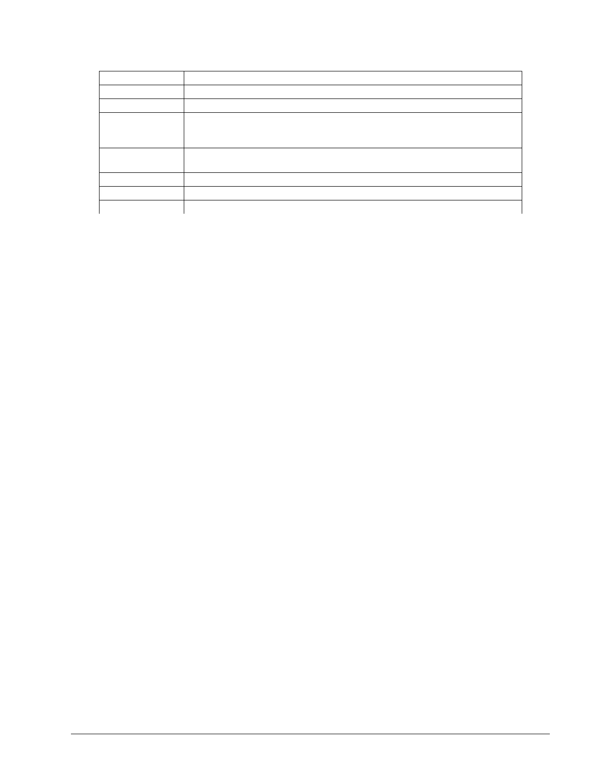
Command Description
MT
Configures an axis for use with either a stepper or servo motor
AG
Amplifier gain (A/V for servos or A/Phase for steppers)
BR
Will configure an internal servo amplifier for brushed mode
(Also used to ignore halls when the use of external amplifiers is required in lieu of an
internal)
AU
Configures the current loop update rate
(Can also be used to switch capable amplifiers between chopper and inverter mode)
TL, TK
Limits motor command line output in Volts, thus limiting the current in the amplifier
YA
Stepper drive resolution (microstepping configuration)
LC
Configures stepper motor current at holding or “rest” positions
Table 2.10: Sample of motor and amplifier configuration commands
Step D. If using a servo motor, continue to Step 10. Tune the Servo System, pg 32. If using a stepper, continue
on to Step E.
Step E. Enable and use your motor
A SH will enable the internal amplifier and a MO will disable the internal amplifier. Once enabled, you can send
DMC motion commands to move the motor, see Chapter 6 Programming Motion, pg 71 for details.
Step 8a. Commutation of 3-phased Brushless Motors
If a motor is not correctly commutated it will not function as expected. Commutation is the act of properly getting
each of the 3 internal phases of a servo motor to switch at the correct time to allow smooth, 360 degree rotation in
both directions. The two most common methods for doing so are trapezoidal commutation (use of Hall sensors)
and through position sensor algorithms (sinusoidal commutation, no Halls required).
The following sections provide a brief description and guide on how to perform either commutation method
including wiring and configuration commands. These sections are divided into Trapezoidal and Sinusoidal:
Trapezoidal Commutation
The following amplifiers support trapezoidal commutation:
A1 – AMP-430x0 (-D3040,-D3020), pg 213
A3 – AMP-43240 (-D3240), pg 222
Trapezoidal commutation is a time-tested way for determining the motor location within a magnetic cycle;
However, interpretation of hall sensor feedback varies between motor manufactures requiring the user to find the
correct wiring combination.
Before wiring the motor the user should determine which is easier: Wiring the hall sensors or wiring the motor
phases. This method will start with wiring both the halls and motor phases at random then trying each of the 6
wiring combinations of either the halls or the motor phases (not both). For each combination, the user will be
asked to check the open-loop velocity in both directions . Some of the wiring combinations will lead to no motion,
this is expected. The following directions are given using the A-axis as an example.
1. Wire the 3 motor phase wires and 3 hall sensors randomly. Do not connect the motor to any external
mechanics or load, a free spinning motor is required for testing. Take all safety precautions necessary as the
motor tests below will result in a runaway condition.
2. Set the PID’s and BR to zero and disable off-on-error (OE) to allow for full rotation of the motor in open-
loop. Issue the following commands from a Galil terminal program:
KPA= 0
Chapter 2 Getting Started ▫ 24 DMC-40x0 User Manual