Page 7
3E4720 Gallagher T12 Reader | Edi on 12 | May 2023
Copyright © Gallagher Group Limited
4 InstallaƟ on
ATTENTION: This equipment contains components that can be damaged by
electrosta c discharge. Ensure both you and the equipment are earthed before
beginning any servicing.
The Gallagher T12 Reader is designed to be mounted on a standard Bri sh electrical fl ush box, or any
solid fl at surface. However installa on on metal surfaces, par cularly those with a large surface area
will reduce read range. The extent to which the range is reduced will depend upon the type of metal
surface.
Note: Considera on should be given to the installa on environment when using Bluetooth® enabled
readers, as the read range may be reduced.
The recommended moun ng height for the reader is 1.1 m (3.6 ) from the fl oor level to the centre of
the reader device. However this may vary in some countries and you should check local regula ons for
varia ons to this height.
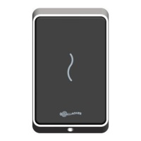
1. Ensure the building cable has been run out through the fl ush box.
If you are not moun ng to a fl ush box, use the reader bezel as a guide to drill all fi ve holes. Drill
the 13 mm (1/2 inch) diameter centre hole (this is the centre hole for which the building cable
will exit the moun ng surface) and the four fi xing holes.
2. Run the building cabling out through the centre hole and through the reader bezel.
3. Secure the bezel to the fl ush box using the two M3.5 screws provided. It is important the bezel
of the reader is fl ush with and ght against the moun ng surface.
If you are not moun ng to a fl ush box, secure the bezel to the moun ng surface using the four
fi xing screws provided.
Note: It is strongly recommended that you use the screws provided. If an alterna ve screw is
used, the head must be no larger nor deeper than that of the screw provided.
Note: Ensure the centre hole allows the cable to run freely out through the moun ng surface, so
that the reader facia can clip into the bezel.
Bezel
Building cable
M3.5 screw
M3.5 screw
4. Connect the reader tail extending from the facia assembly to the building cable. Connect the
wires for the appropriate reader you wish to interface, either an HBUS Reader or a Cardax IV
Reader, as shown in the following diagrams.
Notes:
• Bluetooth® enabled readers must be connected as HBUS Readers.
• Gallagher High Sec readers must be connected as HBUS Readers. Gallagher High Sec
reader connect to the Gallagher High Sec Controller 6000 (C305101) only.