16
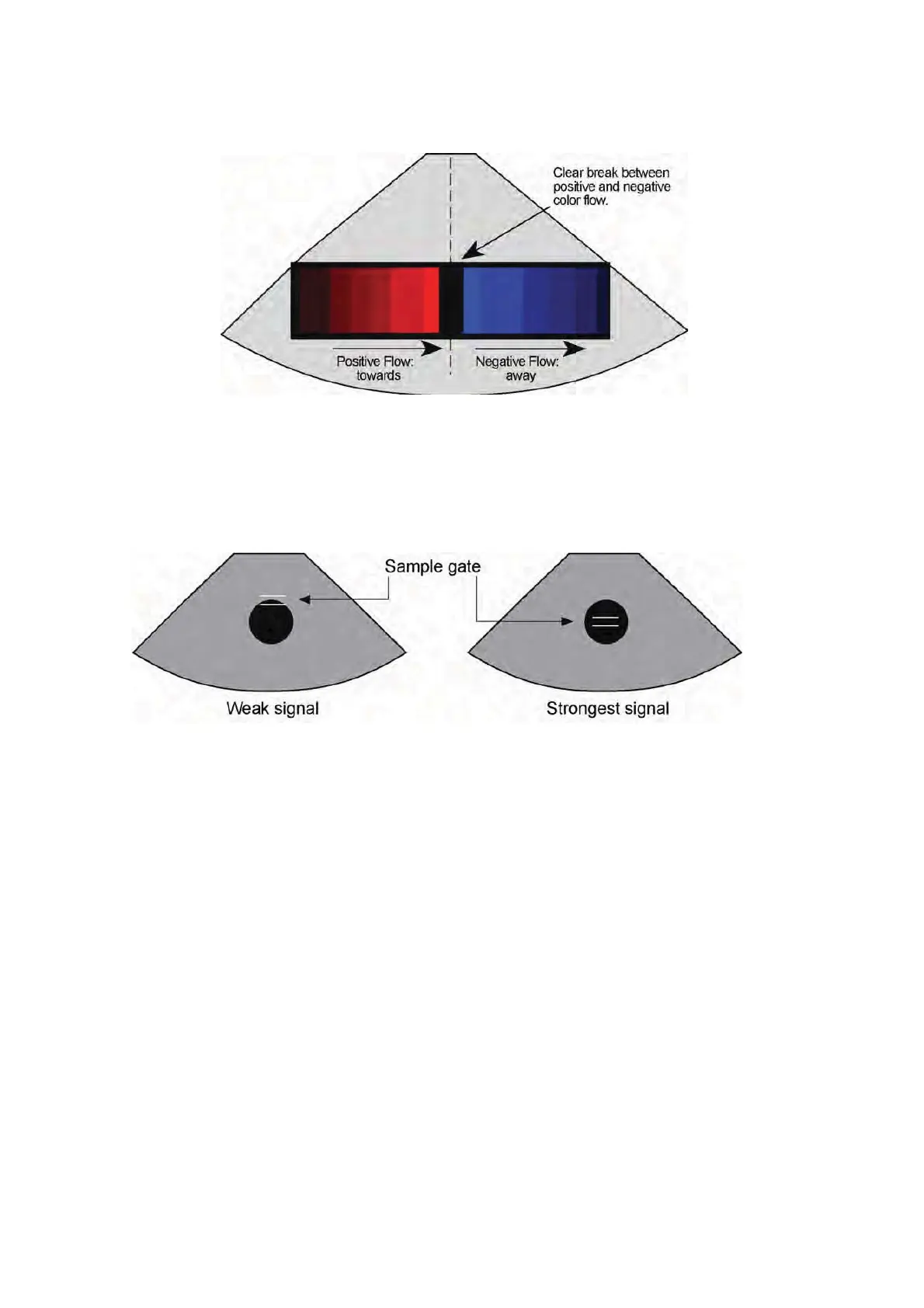
4. Scan the blood vessel so that the image displayed is a cross-section of the vessel.
With the flow phantom in constant flow mode, place the cursor at several locations
across the vessel and measure the velocity. The highest velocity reading should
occur when the cursor is placed in the center of the vessel. This test evaluates the
accuracy of the sample gate positioning.
5. Scan the vessel along its length with the flow phantom in continuous flow mode.
Close the sample gate to the smallest opening. Compare the displayed peak value
on the scanner with the estimated peak value, corresponding to the displayed flow
on the control module, to determine the accuracy of the maximum velocity readout.
Use the provided chart to translate “Flow” measurements into “Estimated Speed”.
6. Use color tagging techniques to verify the maximum velocity readout. By using
tagging techniques, isolate each flow rate and identify the maximum flow rate. This
value should be near the value in step 5.
7. When you have finished scanning the phantom, completely clean off the coupling
gel or water with a soft cloth or paper towel. Turn off the Doppler Mode and close
the cover to protect the phantom.