Do you have a question about the Gardner Denver AirSmart VS20A and is the answer not in the manual?
Explains DANGER symbols and their meaning for high-risk hazards.
Explains CAUTION symbols and their meaning for low-risk hazards.
Details critical safety measures to prevent severe injury or death.
Outlines precautions to prevent equipment damage and serious injury.
Explains the helical rotor compression process and its stages.
Details the path of air from intake to discharge.
Describes how oil is used for lubrication, cooling, and sealing.
Checks for damage upon receipt and reporting of issues.
Proper methods for lifting and transporting the compressor package.
Guidelines for selecting an optimal installation site with proper ventilation.
Requirements for the compressor base and mounting.
Steps for draining oil from the reservoir.
Capacity guidelines for auxiliary air receivers.
Instructions for piping the moisture separator and drain.
Notes on the air filter assembly and enclosure integration.
Details on connecting the discharge service line and check valves.
Information on the blow down valve and its venting.
Guidance on connecting power supply and wiring the unit.
Criteria for selecting appropriate electrical wire sizes.
When a line reactor is required for power supply conditioning.
Ensuring proper grounding according to electrical codes.
Information on motor bearing lubrication for satisfactory operation.
Essential checks and servicing before initial compressor operation.
Procedure for checking and adding compressor oil.
How to inspect and replace the air filter element.
Checking the coupling element for signs of wear.
Ensuring correct wiring of the unit and components.
Confirming proper grounding for controller function.
Verifying correct rotation direction for electric motors.
Instructions for setting target, unload, and load pressures.
Procedure to adjust the compressor's operating target pressure.
Adjusting the pressure points for unloading and loading the compressor.
Step-by-step guide for starting the compressor.
How to safely stop the compressor and its associated systems.
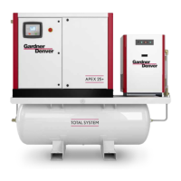
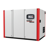
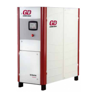
Overview of the compressor package components and systems.
Details the integration and functions of the AirSmart controller.
Explanation of the variable frequency drive and motor operation.
Diagram showing system piping and instrument connections.
Electrical schematic for 460-volt configurations.
Electrical schematic for 200/230-volt configurations.
Electrical schematic for 575-volt configurations.
How lubricating oil absorbs heat, lubricates parts, and seals clearances.
Details on AEON 9000SP lubricant and its properties.
Properties of AEON 9000SP lubricating coolant.
Avoiding water vapor condensation and identifying valve malfunctions.
Checking and adjusting the oil level using the sight glass.
Procedure for replenishing oil level as needed.
Recommended intervals for changing the compressor lubricant.
Steps for draining and cleaning the oil system.
Procedure for refilling the system after draining.
Importance and replacement intervals for the oil filter.
How the valve mixes oil to control discharge temperature.
How the oil mixing valve operates during normal conditions.
Adjusting auto timer for low demand cycles to prevent condensation.
Functions of the oil/air separation system and coalescing element.
Expected oil carryover levels and factors affecting performance.
Controller tracking of pressure differential for element service.
Procedures for replacing or inspecting the coalescing element.
How heat exchangers reject compression heat using air or water.
Cleaning procedures for air-cooled cores to maintain efficiency.
Function and servicing of the water separator.
How the air filter cleans incoming air for efficient operation.
Steps for inspecting and replacing the air filter element.
Description of the motor and compressor drive coupling.
Procedures for inspecting and replacing the coupling element.
Handling coupling hubs with transitional interference fits.
Steps for mounting and installing coupling hubs.
Procedure for removing coupling hubs, including interference fits.
Maintains reservoir pressure and prevents backflow.
Steps for inspecting the minimum pressure/check valve assembly.
Allows compressor readiness and quick response to air demand.
Checking valve seals for wear and tear.
Protects components from over-pressurization.
Procedure for testing the pressure relief valve annually.
Ensuring electronics operate efficiently by keeping filters clean.
Steps for inspecting and cleaning ventilation filter elements.
Recommended grease, re-greasing intervals, and procedure.
Details on recommended grease for the main motor.
Lubrication intervals based on service type and operating conditions.
Daily, weekly, and periodic maintenance tasks.
Tasks to perform every 1000 hours of operation.
Tasks to perform every 8000 hours or as per oil analysis.
Annual checks including heat exchangers, relief valve, and couplings.
Possible causes and remedies for a compressor that won't start.
Causes and remedies for premature compressor shutdown.
Causes and remedies for problems with unloading or loading.
Causes and remedies for rapid load/unload cycles.
Causes and remedies for slow compressor startup.
Causes and remedies for reduced air output and pressure.
Causes and remedies for high oil usage.
Causes and remedies for high air and oil temperatures.
Causes and remedies for VFD shutdown due to overheating.
Causes and remedies for oil found in the intake filter area.
Causes and remedies for oil being carried over with the air.
General terms, conditions, and exclusions of the product warranty.
Specific warranty durations for different components.
Warranty coverage for airends, including shaft seals.
Warranty for controller, VFD, motor, and other major parts.
Exclusions and limitations of warranties provided.
| Type | Rotary Screw |
|---|---|
| Motor Power | 20 HP |
| Drive Type | Direct Drive |
| Control | AirSmart Controller |
| Max Pressure | 125 psi |
| Voltage | 208-230/460V |
| Dimensions | 48 inches |