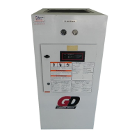
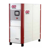
Do you have a question about the Gardner Denver INTEGRA AIRSMART EFC99J and is the answer not in the manual?
Guidance on specifying and ordering replacement parts from authorized distributors.
Information on warning, prohibition, and safety labels used in the manual.
Defines hazard levels for Danger, Warning, and Caution labels.
Lists mandatory actions and prohibitions for safe operation.
Provides general safety advice and best practices for operating the compressor.
Describes the rotary screw compressor and its compression principle.
Explains the air flow path and the compressor's oil system.
Covers initial inspection, lifting, and general installation requirements.
Details on lifting procedures, site selection, and air-cooled unit specifics.
Recommendations for compressor room layout and foundation requirements.
Provides guidelines for installing units in cold climates.
Notes on auxiliary air receivers, moisture separators, and piping.
Chart specifying pipe size based on inlet line length.
Details on connecting the discharge service line and valve usage.
Information on standard unit wiring, motor connections, and safety.
Details on proper grounding according to electrical codes.
Step-by-step procedure for regreasing electric motor bearings.
Lists recommended grease manufacturers and trade names.
Provides relubrication intervals based on service type.
Essential checks and procedures before initial unit startup.
Covers checks for oil, air filter, piping, electrical, and grounding.
Checking motor rotation and setting system pressure.
Refers to Section 4 for details on control system operating modes.
Ensuring enclosure panels are secure and latched.
Step-by-step procedure for starting the unit when cold.
Covers daily checks and the procedure for stopping the unit.
Step-by-step guide to setting the compressor's target pressure.
Instructions for adjusting unload and load pressure settings.
Overview of the compressor's control system and AirSmart operation.
Details on the AirSmart controller, its functions, and keypad usage.
Explains the relief valve's purpose and how to test its operation.
Describes oil level gauge, minimum pressure/check valve.
Details inlet, unloader, check, and blowdown solenoid valves.
Explains system pressure transducers and air filter vacuum switch.
Describes discharge and reservoir thermistors.
Information on the emergency stop pushbutton's function and location.
Describes the main starter's role in motor control and protection.
Procedure for replacing seals in the minimum pressure/check valve.
Wiring diagram for Wye Delta configurations at 200/460V.
Wiring diagram for Wye Delta configurations at 230V.
Wiring diagram for Full Voltage configurations at 460V.
Wiring diagram for Full Voltage configurations at 200V.
Wiring diagram for Full Voltage configuration at 20 HP, 230V.
Wiring diagram for Full Voltage configurations at 25-30 HP, 230V.
Wiring diagram for Less Starter configurations at 200-460V.
Wiring diagram for Less Starter configuration at 230V.
Wiring diagram for Wye Delta configuration at 575V.
Wiring diagram for Full Voltage configuration at 575V.
Wiring diagram for Less Starter configuration at 575V.
Explains the compressor oil system, including cooling and lubrication.
Details Gardner Denver's recommended AEON lubricants for the compressors.
Guidelines for operation in high and cold temperature environments.
Procedure for checking and adding oil to the reservoir.
Step-by-step process for draining and cleaning the compressor oil system.
Instructions for safely filling the oil reservoir.
Steps for upgrading or changing the type of compressor lubricant.
How to read the oil level gauge and address moisture in oil.
Procedure for replacing the compressor oil filter element.
Details on the oil cooler and thermostatic mixing valve.
Information on the oil reservoir and the air/oil separator.
Guidance on interpreting pressure differential for separator service.
Notice regarding element rupture or heavy oil carryover.
Step-by-step instructions for removing the oil separator element.
Procedure for servicing the standard duty air filter.
Detailed steps for replacing the air filter element.
Guidance on inspecting element condition and proper handling.
Procedure for replacing compressor drive belts.
Instructions for aligning motor and airend sheaves.
Steps for replacing the compressor sheave and tapered bushing.
Method for checking and adjusting belt tension.
Table showing deflection force and deflection for belt tension.
Lists various maintenance actions and their service check criteria.
Details maintenance tasks required every 8 and 125 hours of operation.
Specifies maintenance tasks required every 1000, 4000 hours, and yearly.
A table summarizing maintenance actions and their intervals.
Troubleshooting common causes for startup failures and short run times.
Addresses problems with compressor loading, unloading, and cycling.
Solutions for excessive unloaded running and slow startup.
Troubleshooting low air delivery, high discharge temp, and oil consumption.
Identifies causes of oil carryover and provides corrective actions.
Explains how voltage issues affect compressor performance and protection.
General terms, conditions, and limitations of the product warranty.
Details specific warranty periods for airends, motors, and other components.
Covers warranty labor, transportation costs, and legal disclaimers.
| Brand | Gardner Denver |
|---|---|
| Model | INTEGRA AIRSMART EFC99J |
| Category | Air Compressor |
| Language | English |


