Do you have a question about the Garmin COMPACT REACTOR 40 and is the answer not in the manual?
Outlines necessary steps and considerations before starting the autopilot installation process.
Steps to identify suitable mounting locations for the CCU, considering various factors.
Procedure to test potential CCU mounting locations for magnetic interference using a compass.
Guidelines for mounting the pump, including orientation and hose connections.
Instructions for mounting the Shadow Drive sensor in the hydraulic steering system.
Recommendations for mounting and connecting the alarm unit.
Information on connecting the autopilot to an NMEA 2000 network.
Schematic showing hydraulic connections for a single-helm autopilot system.
Guidance on installing the helm control, or connecting to a chartplotter.
Detailed steps for physically mounting the CCU unit onto a surface.
Steps to mount the ECU unit onto a suitable surface.
Instructions for wiring the ECU to the boat's power source, including fuse requirements.
Steps to mount the pump unit securely onto a surface.
Detailed guide for connecting hydraulic hoses to the pump and steering system.
Instructions for routing and connecting the CCU cable to the ECU.
Steps to connect the Shadow Drive sensor into the boat's hydraulic steering lines.
Procedure for connecting the Shadow Drive sensor wiring to the CCU.
Instructions for mounting and wiring the autopilot alarm unit.
Information about integrating the autopilot with an NMEA 2000 network.
Information on configuring and tuning the autopilot system for boat dynamics.
Instructions for applying corrosion blocker to the pump for longevity.
Detailed specifications for the Compact Pump and CCU components.
List of PGNs transmitted and received by the CCU for NMEA 2000 communication.
Information regarding PGNs for the helm control, directing to owner's manual.
Details about low ECU voltage errors, cause, and autopilot actions.
Information on lost navigation data, its impact, and autopilot response.
Description of issues when the helm control loses connection with the CCU.
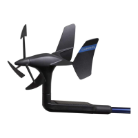
Specific warning for loss of wind data for sailboat installations.
Details about high ECU voltage errors, cause, and autopilot actions.
Information on rapid ECU voltage drops, cause, and system response.
Details about high ECU temperature warnings and system shutdown.
Description of communication loss between ECU and CCU, and resulting actions.
Contact information and resources for obtaining support from Garmin.
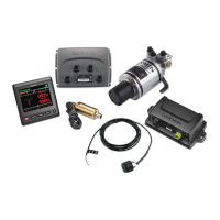
The Garmin Compact Reactor 40 Hydraulic Autopilot System is a sophisticated marine navigation tool designed to enhance vessel control and simplify steering tasks. This system comprises several key components, including a Course Computer Unit (CCU), an Electronic Control Unit (ECU), a hydraulic pump, and an optional helm control or compatible Garmin chartplotter for configuration and control.
The primary function of the Compact Reactor 40 Hydraulic Autopilot System is to provide automated steering for boats with hydraulic steering systems. It allows the vessel to maintain a set course, follow routes, and perform various steering maneuvers with precision, reducing the need for constant manual input from the operator. The system integrates with the boat's existing hydraulic steering lines, using a hydraulic pump to actuate the steering cylinder and control the rudder.
The CCU acts as the central sensor for the autopilot, continuously monitoring the boat's heading, attitude, and other critical navigational data. It processes this information to determine the necessary steering adjustments. The ECU serves as the control hub for the hydraulic pump, translating commands from the CCU into precise movements of the pump to steer the boat. The hydraulic pump, connected to the boat's steering cylinder, is responsible for the physical execution of steering commands.
An optional Shadow Drive sensor can be integrated into the hydraulic steering line. This sensor detects when the helm is manually turned, temporarily suspending autopilot control to allow for immediate manual override. This feature ensures that the operator can quickly regain control of the vessel in any situation, prioritizing safety and responsiveness.
The system is designed to be highly adaptable, allowing for installation in both single-helm and dual-helm configurations. It connects to a NMEA 2000 network, which facilitates communication between the autopilot components and other marine electronics, such as chartplotters, GPS devices, wind sensors, and water-speed sensors. This network integration enables advanced autopilot features and allows for system configuration and control through a compatible Garmin chartplotter if a dedicated helm control is not used.
The Compact Reactor 40 Hydraulic Autopilot System is intended to simplify navigation and reduce operator fatigue during long voyages or when precise course-keeping is required. Users are responsible for the safe and prudent operation of their vessel, and the autopilot is presented as a tool to enhance, not replace, safe boating practices. Operators are advised to always be prepared to regain manual control and to avoid leaving the helm unattended.
Before initial use, the autopilot system requires careful installation and configuration. This includes mounting the CCU, ECU, and hydraulic pump in appropriate locations, connecting all electrical and hydraulic lines, and bleeding the hydraulic system to remove air. The CCU mounting location is particularly important, as it should be near the center of rotation of the boat and away from sources of magnetic interference to ensure optimal performance.
Once installed, the system must be configured and tuned to the specific dynamics of the boat using the Dockside Wizard and Sea Trial Wizard, typically accessed through the helm control or a compatible Garmin chartplotter. These wizards guide the user through a series of steps to calibrate the autopilot for accurate and stable steering.
The autopilot can be used for various steering tasks, including maintaining a straight course, following predefined routes, and executing turns. The Shadow Drive sensor provides a seamless transition between autopilot and manual steering, allowing the operator to take control without disengaging the autopilot system. An audible alarm system provides alerts for various operational conditions, such as low ECU voltage, loss of navigation data, or communication errors between components, ensuring the operator is aware of critical system statuses.
The system's integration with the NMEA 2000 network allows for flexible control and data sharing. If a dedicated helm control is not part of the package, a compatible Garmin chartplotter can serve as the primary interface for configuring and controlling the autopilot, providing a unified navigation experience.
Proper maintenance is crucial for ensuring the longevity and reliable operation of the Compact Reactor 40 Hydraulic Autopilot System. A key maintenance recommendation is the regular application of a marine-rated corrosion blocker to the hydraulic pump. This should be done at least twice yearly, especially after all hydraulic and electrical connections have been made and the hydraulic system has been bled. This protective measure helps prevent corrosion in the harsh marine environment, extending the life of the pump and its components.
When connecting electrical cables, particularly the ECU power cable, it is important to ensure that the in-line fuse holder is not removed, and the appropriate fuse is in place. This protects against fire or overheating and is a condition for maintaining the product warranty. Additionally, applying dielectric grease to the pin holes on cable connectors is recommended to prevent corrosion, particularly when the autopilot system is used in saltwater. This simple step helps maintain good electrical contact and prevents signal degradation over time.
The hydraulic system itself requires periodic bleeding to remove any air that may accumulate, which can affect steering performance. The manual provides a general procedure for bleeding the hydraulic steering system, emphasizing the importance of referring to the steering system manufacturer's instructions for more specific guidance. Ensuring all hose connections are complete and fully tightened before bleeding is also critical.
Regular checks of the system's components for any signs of wear, damage, or loose connections are also part of good maintenance practice. Addressing any issues promptly can prevent more significant problems down the line. The system's design, with components like the ECU mounted in locations protected from submersion or wash-down, also contributes to its overall durability and reduced maintenance needs.
| WEIGHT | 1.2 lbs (0.54 kg) |
|---|---|
| WATER RATING | IPX7 |
| Compass | Yes |
| Wi-Fi | No |
| NMEA 2000 Support | Yes |
| OPERATING TEMPERATURE | -15° C to 55° C (5° F to 131° F) |
| POWER INPUT | 10 to 32 Vdc |
| Power Supply | 10 to 32 Vdc |
| Dimensions | 4.5" x 4.5" x 2.4" (11.4 x 11.4 x 6.1 cm) |