REACTOR
™
40 MECHANICAL
INSTALLATION
INSTRUCTIONS
Important Safety Information
WARNING
See the
Important Safety and Product Information guide in the
product box for product warnings and other important
information.
You are responsible for the safe and prudent operation of your
vessel. The autopilot is a tool that enhances your capability to
operate your boat. It does not relieve you of the responsibility of
safely operating your boat. Avoid navigational hazards and
never leave the helm unattended.
Always be prepared to promptly regain manual control of your
boat.
Learn to operate the autopilot on calm and hazard-free open
water.
Use caution when operating the autopilot near hazards in the
water, such as docks, pilings, and other boats.
CAUTION
When in use, beware of hot surfaces on the heat-sink, motor,
and solenoid components.
When in use, beware the risk of entrapment or pinching from
moving parts.
Failure to install and maintain this equipment in accordance with
these instructions could result in damage or injury.
NOTICE
To avoid damage to your boat, the autopilot system should be
installed by a qualified marine installer. Specific knowledge of
marine steering and electrical systems is required for proper
installation.
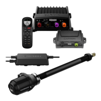
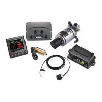
Installation Preparation
The autopilot system consists of multiple components. You
should familiarize yourself with all of the component mounting
and connection considerations before beginning installation. You
must know how the components operate together in order to
correctly plan the installation on your boat.
You can consult the layout diagrams to help understand the
mounting and connection considerations.
You should lay out all of the components on the boat as you
plan the installation to make sure your cables will reach each
component. If needed, extension cables (sold separately) for
various components are available from your Garmin
®
dealer or
from www.garmin.com.
You should record the serial number of each component for
registration and warranty purposes.
Tools and Supplies Needed
• Safety glasses
• Drill and drill bits
• 90 mm (3.5 in.) hole saw or a rotary cutting tool (for installing
an optional helm control)
• Wire cutters/strippers
• Phillips and flat screwdrivers
• Cable ties
• Waterproof wire connectors (wire nuts) or heat-shrink tubing
and a heat gun
• Marine sealant
• Portable or handheld compass (to test for magnetic
interference)
NOTE:
Mounting screws are provided for the main components
of the autopilot system. If the provided screws are not
appropriate for the mounting surface, you must provide the
correct types of screws.
Power and Data Layout
WARNING
When connecting the power cable, do not remove the in-line
fuse holder. To prevent the possibility of injury or product
damage caused by fire or overheating, the appropriate fuse
must be in place as indicated in the product specifications. In
addition, connecting the power cable without the appropriate
fuse in place voids the product warranty.
Item Description Important Considerations
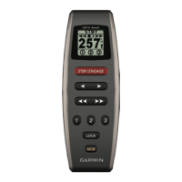
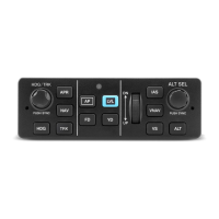
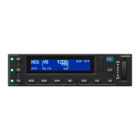
Helm control A dedicated helm control is not included in all
autopilot packages. If you install the autopilot
without a dedicated helm control, the autopilot
CCU must be connected to the same NMEA
2000
®
network as a compatible Garmin
chartplotter to configure and control the autopilot
system.
Helm control
data cable
You should install this cable only if you are
connecting the autopilot to optional NMEA
®
0183
devices, such as a wind sensor, a water-speed
sensor, or a GPS device (NMEA 0183
Connection Considerations, page 8).
NMEA 2000
power cable
You should install this cable only if you are
building a NMEA 2000 network. Do not install this
cable if there is an existing NMEA 2000 network
on your boat.
You must connect the
NMEA 2000 power cable
to a 9 to 16 Vdc power source.
NMEA 2000
network
You must connect the helm control or compatible
Garmin
chartplotter and the CCU to a NMEA
2000 network using the included T-connectors
(
NMEA 2000 Connection Considerations,
page 4)
.
If there is not an existing
NMEA 2000 network on
your boat, you can build one using the supplied
cables and connectors (
Building a Basic NMEA
2000 Network for the Autopilot System,
page 7)
.
April 2019
190-02317-02_0B