EasyManua.ls Logo

Garmin GMC 7 Series User Manual

Garmin GMC 7 Series
34 pages
To Next Page IconTo Next Page
Page #1 background imageLoading...
Page #1 background image
190-00303-70 September, 2008 Revision F
(GMC 710 Shown)
GMC 7X
X
Installation Manual
Question and Answer IconNeed help?

Do you have a question about the Garmin GMC 7 Series and is the answer not in the manual?

Garmin GMC 7 Series Specifications

General IconGeneral
BrandGarmin
ModelGMC 7 Series
CategoryAutopilot System
LanguageEnglish

Summary

TSO/ETSO Compliance (GMC 705)

GMC 710 TSO/ETSO Compliance

GMC 715 TSO/ETSO Compliance

TSO/ETSO Deviations (GMC 705 & 710)

GMC 715 TSO/ETSO Deviations

INSTALLATION OVERVIEW

Cabling & Wiring

2.4 Cabling & Wiring

Provides guidelines for wiring gauge, connections, and routing for GMC 7XX installation.

Cooling Air and Mounting Requirements

2.6 Mounting Requirements

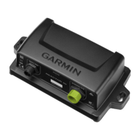
Details mounting hardware and procedures using GDU 1040 hardware and fasteners.

INSTALLATION PROCEDURE

3.2 Wiring Harness Installation

Guidance on fabricating wiring harnesses and connecting to the 15-pin D subminiature connector.

Backshell, Unit, and Post-Installation Procedures

3.4 Unit Installation

Describes how to install the GMC 7XX unit flush with the instrument panel using locking studs.

3.5 Post Installation Configuration & Checkout

Notes that GMC 7XX requires configuration and checkout per approved procedures.

SYSTEM INTERCONNECTS

4.1 Pin Function List

Details pin assignments for the J7101 connector on the GMC 7XX.

4.1.1 P7101 Connector Pinout

Provides a view of the J7101 connector and its pinout from the back of the unit.

4.2 Power Functions

Covers the power input requirements and functions for the GMC 7XX.

4.2.1.1 Aircraft Power

Lists pin names and connector pins for aircraft power inputs.

Serial Data Connections

4.3 Serial Data Electrical Connections

Lists electrical connections for serial data, focusing on RS-232.

4.3.1.1 RS-232

Provides pin names, connector pins, and I/O for RS-232 connections.

GMC 705 Cutout Drawing

Figure A-1. GMC 705 Cutout Drawing

Provides panel cutout dimensions for the GMC 705 unit.

GMC 710 Cutout Drawing

Figure A-2. GMC 710 Cutout Drawing

Provides panel cutout dimensions for the GMC 710 unit.

GMC 715 Cutout Drawing

GMC 705 Outline Drawing

GMC 710 Outline Drawing

GMC 715 Outline Drawing

GMC 705 Installation Drawing

GMC 710 Installation Drawing

GMC 715 Installation Drawing

APPENDIX B: INTERCONNECT EXAMPLE

Related product manuals