Item Description Important Considerations
ECU
CCU You can mount the CCU in a non-submerged
location near the center of the boat, in any
orientation (CCU Mounting and Connection
Considerations, page 3).
Mount the CCU away from sources of magnetic
interference.
ECU power
cable
You must connect the ECU to a 12 to 24 Vdc
power source. To extend this cable, use the
correct wire gauge (Power Cable Extensions,
page 4).
CCU cable To extend this cable to reach the ECU, you may
need to use cable extensions (sold separately)
(CCU Mounting and Connection Considerations,
page 3).
You must connect this cable to the alarm and the
Shadow Drive
™
sensor.
NOTE: The Shadow Drive sensor is optional and
sold separately
Drive unit This diagram shows only the electrical
connections for the drive unit (sold separately).
Detailed installation instructions are included with
the drive unit.
If you purchased a drive unit from Garmin, it
includes the necessary power and feedback
cables.
Drive unit
power and
feedback
cables
The drive unit power cable cannot be cut or
extended. If you are using the autopilot with a
drive unit not sold by Garmin, you must use a
drive unit power cable (sold separately)
(Connecting to an Existing Drive Unit, page 5).
If you are using the autopilot with a solenoid drive
unit, you must use a solenoid power cable (sold
separately) (Connecting to a Solenoid Drive Unit,
page 5).
If you are using the autopilot with a drive unit not
sold by Garmin or a solenoid drive unit, you must
install a Garmin rudder feedback sensor
(recommended) or connect to an existing rudder
feedback sensor using a rudder feedback cable
(sold separately) (Drive Unit Installation,
page 5).
Alarm The alarm provides audible alerts from the
autopilot system, and you should install it near
the primary helm station (Installing the Alarm,
page 6).
Shadow Drive
sensor
connection
(optional)
The Shadow Drive sensor is an optional
accessory that can be used only on a boat with a
hydraulic steering system (Installing the Shadow
Drive Sensor, page 6).
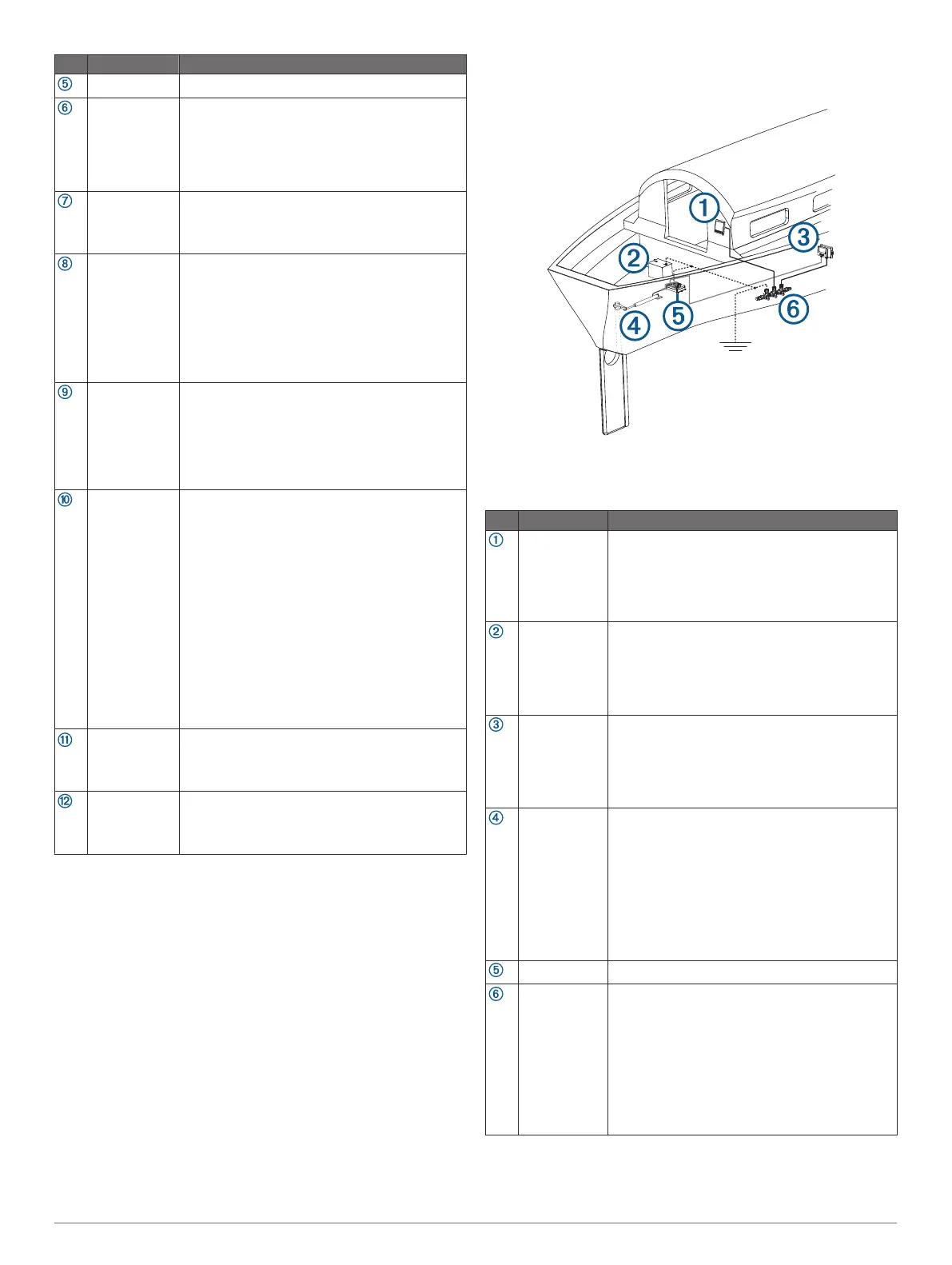
Component Layout
Single-Helm Layout
NOTE: This diagram is for planning purposes only. If needed,
specific connection diagrams are included in the detailed
installation instructions for each component.
Item Description Important Considerations
Helm control A dedicated helm control is not included in all
autopilot packages. If you install the autopilot
without a dedicated helm control, the autopilot
CCU must be connected to the same NMEA 2000
network as a compatible Garmin chartplotter to
configure and control the autopilot system.
12 to 24 Vdc
battery
You must connect the ECU to a 12 to 24 Vdc
power source. To extend this cable, use the
correct wire gauge (Power Cable Extensions,
page 4).
You must connect the NMEA 2000 power cable to
a 9 to 16 Vdc power source.
CCU You can mount the CCU in a non-submerged
location near the center of the boat, in any
orientation (CCU Mounting and Connection
Considerations, page 3).
Mount the CCU away from sources of magnetic
interference.
Drive unit The drive unit power cable cannot be cut or
extended.
If you are using the autopilot with a drive unit not
sold by Garmin, you must use a drive unit power
cable (sold separately) (Connecting to an Existing
Drive Unit, page 5).
If you are using the autopilot with a solenoid drive
unit, you must use a solenoid power cable (sold
separately) (Connecting to a Solenoid Drive Unit,
page 5).
ECU
NMEA 2000
network
You must connect the helm control or compatible
Garmin chartplotter and the CCU to a NMEA
2000 network using the included T-connectors
(NMEA 2000 Connection Considerations,
page 4).
If there is not an existing NMEA 2000 network on
your boat, you can build one using the supplied
cables and connectors (Building a Basic NMEA
2000 Network for the Autopilot System,
page 7).
Mounting and Connection Considerations
The autopilot components connect to each other and to power
using the included cables. Ensure that the correct cables reach
2