EasyManua.ls Logo

Garmin Reactor 40 Kicker User Manual

Garmin Reactor 40 Kicker
28 pages
To Next Page IconTo Next Page
Page #1 background imageLoading...
Page #1 background image
REACTOR
40 KICKER
INSTALLATION INSTRUCTIONS
Important Safety Information
WARNING
See the Important Safety and Product Information guide in the product box for product warnings and other
important information.
You are responsible for the safe and prudent operation of your vessel. The autopilot is a tool that enhances your
capability to operate your boat. It does not relieve you of the responsibility of safely operating your boat. Avoid
navigational hazards and never leave the helm unattended.
Always be prepared to promptly regain manual control of your boat.
If your motor features a kill switch, you should know how to operate it in case of an emergency. If your motor
does not feature a kill switch, you should install one before installing the autopilot system.
Learn to operate the autopilot on calm and hazard-free open water.
Use caution when operating the autopilot near hazards in the water, such as docks, pilings, and other boats.
CAUTION
When in use, beware of hot surfaces on the heat-sink, motor, and solenoid components.
When in use, beware the risk of entrapment or pinching from moving parts.
Failure to install and maintain this equipment in accordance with these instructions could result in damage or
injury.
Installation Preparation
The autopilot system consists of multiple components. You should familiarize yourself with all of the
component mounting and connection considerations before beginning installation. You must know how the
components operate together in order to correctly plan the installation on your boat.
You can consult the layout diagrams to help understand the mounting and connection considerations.
You should lay out all of the components on the boat as you plan the installation to make sure your cables will
reach each component. If needed, extension cables (sold separately) for various components are available from
your Garmin
®
dealer or from www.garmin.com.
You should record the serial number of each component for registration and warranty purposes.
GUID-EF2BAA44-88E5-4854-882C-9A77AB104F05 v3January 2022

Other manuals for Garmin Reactor 40 Kicker

Question and Answer IconNeed help?

Do you have a question about the Garmin Reactor 40 Kicker and is the answer not in the manual?

Garmin Reactor 40 Kicker Specifications

General IconGeneral
Water RatingIPX7
Actuator TypeHydraulic
Steering TypeHydraulic
Communication ProtocolNMEA 2000
InstallationProfessional installation recommended
CompatibilityYamaha, Suzuki, Honda or Mercury kicker motors
Steering TechnologyHydraulic
Wireless RemoteOptional
Operating Temperature-10°C to 55°C
Compatible EnginesYamaha, Suzuki, Honda or Mercury kicker motors

Summary

Important Safety Information

Safety Warnings and Cautions

Highlights critical safety warnings and cautions for operating and installing the autopilot system.

Installation Preparation

Initial Preparation Steps

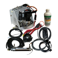
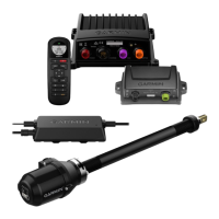
Familiarize yourself with components and plan installation before starting the process.

Tools and Supplies Needed

Power and Data Layout

Helm Control and NMEA 2000 Connectivity

Connect helm control or CCU to NMEA 2000 network with chartplotter.

NMEA 2000 Network Setup

Connect NMEA 2000 power cable to 9-16Vdc source and build network with T-connectors.

ECU and CCU Mounting Guidelines

Mount ECU and CCU in non-submerged locations, away from magnetic interference.

Component Cable Considerations

ECU Power Cable Extension

Connect ECU to 12-24Vdc power source; use correct wire gauge for extensions.

CCU Cable Length Limitation

Connects CCU to ECU; 5m (16ft) long, cannot be extended.

Actuator Power Cable Restrictions

Throttle and steering actuator power cables cannot be cut or extended.

CCU Mounting Location Selection

Finding the Optimal CCU Location

Select CCU location considering center of rotation and avoiding interference sources.

Testing for Magnetic Interference

Use a handheld compass to test potential CCU mounting locations for magnetic interference.

Steering Actuator Installation Overview

Tiller Lock Removal

Remove the tiller lock on the motor if present to avoid installation interference.

Tilt Tube Preparation

Ensure tilt tube is stainless steel; clean tilt tube for proper steering actuator installation.

Installing the Steering Actuator

Preparing the Tilt Tube

Ensure tilt tube is stainless steel; clean tilt tube for proper steering actuator installation.

Installing Steering Actuator in Tilt Tube

Apply grease, feed, screw, and tighten steering actuator into the tilt tube.

Kicker Motor Bracket and Linkage

Bracket Selection by Motor Type

Review table to determine if right-angle or flat bracket is needed for Honda, Mercury, or Yamaha.

Connecting Linkage to Steering Actuator

Connect the linkage rod to the steering actuator according to motor type.

Connecting Actuator Linkage

Linkage Arm to Steering Actuator

Screw linkage pin, install spacer/washers/arm, and secure with R-pin.

CCU to ECU Connection

Route CCU cable connector to ECU and make the connection.

Drive and Throttle Actuator Wiring

Route drive/throttle actuator cables to ECU, ensuring sufficient slack.

NMEA 2000 Network Setup

Building a Basic NMEA 2000 Network

Connect T-connectors, power cable, drop cables, and terminators to build a new NMEA 2000 network.

Connecting to Existing NMEA 2000 Network

Connect CCU and helm control to an existing NMEA 2000 backbone using T-connectors.

Optional NMEA 2000 Devices

Connecting Optional NMEA 2000 Devices

Add T-connectors to network to connect optional NMEA 2000 devices.

Autopilot Configuration

Maintenance Procedures

Steering Actuator Routine Maintenance

Perform regular cleaning and lubrication of the steering actuator and tilt tube.

Freeing a Seized Steering Actuator

Instructions for safely freeing a steering actuator that has become stuck in the tilt tube.

Appendix: NMEA 0183 Information

NMEA 0183 Connection Considerations

Guidelines for connecting NMEA 0183 devices, including wiring and sentence types.

Specifications

Steering Actuator Specifications

Details dimensions, weight, temperature range, material, and water rating for the steering actuator.

CCU Specifications

Details dimensions, weight, temperature range, material, and NMEA 2000 input for the CCU.

ECU Specifications

Details dimensions, weight, temperature range, material, and power input for the ECU.

NMEA 2000 PGN Information

CCU PGN Data

Lists PGNs transmitted and received by the CCU for NMEA 2000 communication.

Helm Control NMEA PGNs

Helm Control PGN Data

Lists PGNs transmitted and received by the Helm Control for NMEA 2000 communication.

Error and Warning Messages

Contacting Garmin Support

Related product manuals