Do you have a question about the Garmin GMA 342 and is the answer not in the manual?
Provides information for planning and design of installation.
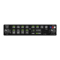
Details the features and capabilities of the GMA 342/345 audio panels.
Covers physical and electrical characteristics, power requirements, and compliance.
Outlines TSO compliance and deviations for the GMA 342/345.
Refers to pilot guides and lists other relevant publications for installation.
Provides information for installation and checkout of the GMA 342/345 audio panel.
Lists catalog part numbers and available accessories for GMA 342/345 units.
Discusses key installation factors including auxiliary inputs, antenna, and pressurized aircraft approvals.
Provides guidance on wire gauge, routing, and precautions for cabling and wiring.
Details requirements for electrical bonding to the aircraft structure for EMI and HIRF protection.
Discusses thermal characteristics and recommendations for cooling the GMA 342/345.
Covers DIP switch, front panel, hardwired configurations, MASQ, sensitivity, and noise options.
Details checking version, creating loader card, and loading software updates.
Discusses minimizing noise from interference and ground loops in audio systems.
Outlines structural support and electrical bond requirements for mounting the unit.
Instructions for unpacking and visually inspecting the unit for damage.
Details electrical connections using 44-pin D-subminiature connectors and required hardware.
Provides instructions for installing the marker beacon antenna and its cable.
Instructions for assembling backshell connectors and grounding system using Shield Block.
Instructions for assembling Garmin's backshell connectors and grounding system.
Step-by-step guide for final installation and assembly of the GMA 342/345 into the rack.
Covers failsafe, transceiver, receiver, music, speaker, and marker beacon checks.
States that maintenance is "on condition" and no periodic maintenance is required.
Explains how to display diagnostics information and interpret fault indications.
Provides steps to disable and re-enable Bluetooth connectivity on the GMA 345.
Describes the two 44-pin connectors (J3401 and J3402) on the rear of the unit.
Lists pin assignments for J3401 and J3402 connectors, grouped by function.
Details the four pins for aircraft power bus inputs and connection recommendations.
Explains lighting bus control and describes RS-232 output characteristics.
Covers mic, COM, alert, receiver, AUX, NAV, failsafe, music, tel, headset, and speaker audio connections.
Lists discrete input pins and their functions, including ICS KEYs and COM Swap.
Describes marker beacon outputs for lamps and sense, and their control.
Discusses compatibility of GMA 340 rack/connectors and required pin modifications.
Details specific pin connections for retrofitting GMA 340 to GMA 342/345.
| Weight | 1.5 lbs (0.68 kg) |
|---|---|
| Dimensions | 6.25 x 5.25 x 1.5 in (158 x 133 x 38 mm) |
| Speaker Outputs | 2 |
| Audio Control | Yes |
| Remote Com Switching | Yes |
| Split Com | Yes |
| Stereo Intercom | Yes |
| Marker Beacon Receiver | Yes |