EasyManuals Logo

Garmin GTX 325 User Manual

Garmin GTX 325
67 pages
To Next Page IconTo Next Page
To Previous Page IconTo Previous Page
Page #35 background imageLoading...
Page #35 background image
190-01499-02 GTX 3x5 TSO Installation Manual
Rev. 1 Page 3-9
Figure 3-1 Figure for Locations of Antennas
3.9 Electrical Bonding
Ensure that the transponder and GPS antennas are electrically bonded to the aircraft.
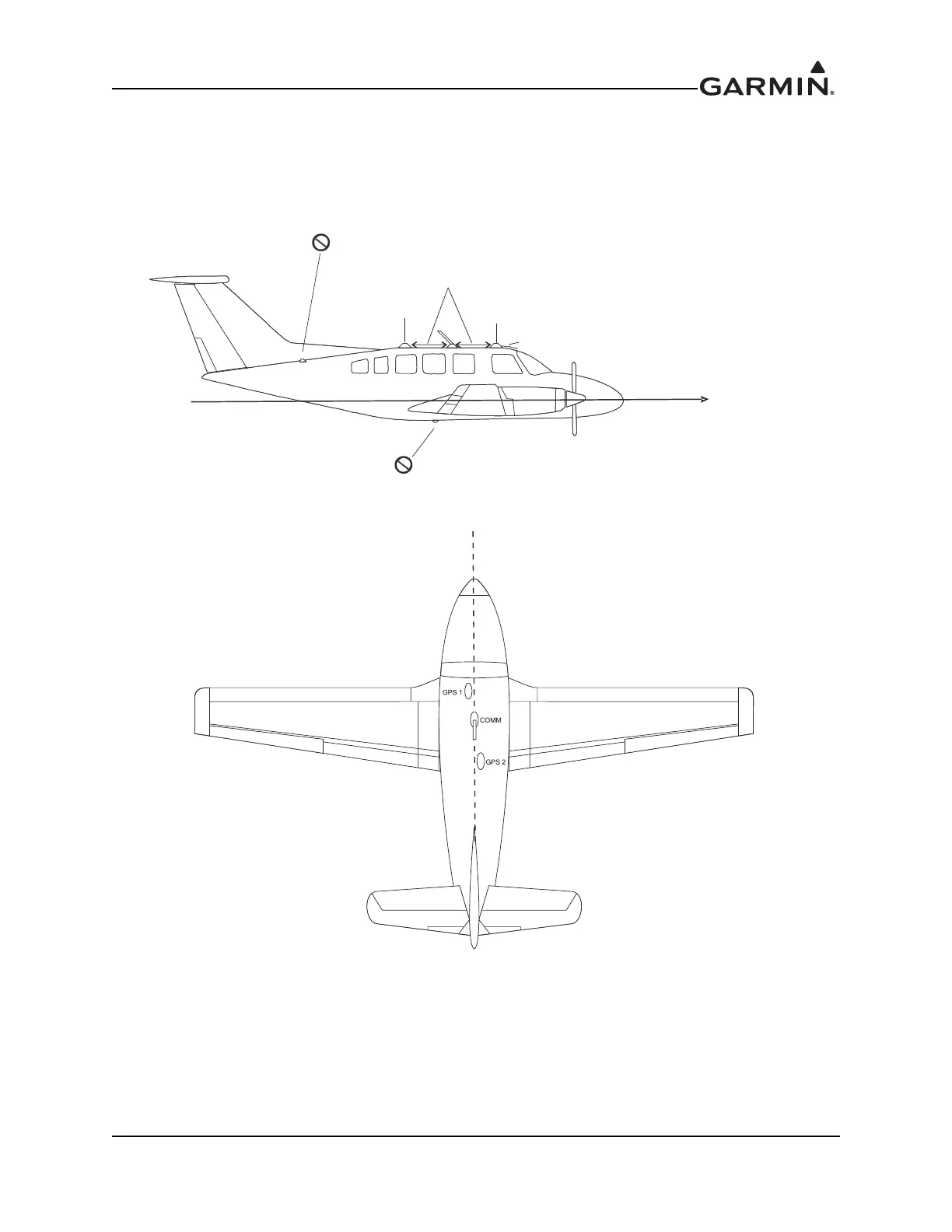
DISTANCE BETWEEN COM AND GPS ANTENNAS
ANTENNA MASKED BY VERTICAL FIN,
T-TAIL, OR DORSAL FIN. ANTENNA NOT
MOUNTED LEVEL WITH RESPECT TO
THE NORMAL FLIGHT ATTITUDE.
GOOD
BETTER
GREATER THAN THREE INCHES
OF WINDSCREEN
NORMAL
FLIGHT
ATTITUDE
ANTENNA MUST BE ON
TOP OF AIRCRAFT
CENTER LINE
SHOULD BE GREATER THAN TWO FEET.
SIDE VIEW
TOP VIEW
GPS ANTENNA OFFSET
FROM CENTERLINE
WITH TYPICAL DUAL
GPS INSTALLATION

Table of Contents

Questions and Answers:

Question and Answer IconNeed help?

Do you have a question about the Garmin GTX 325 and is the answer not in the manual?

Garmin GTX 325 Specifications

General IconGeneral
BrandGarmin
ModelGTX 325
CategoryMarine Radio
LanguageEnglish

Related product manuals